| 501-14 Handles, Locks, Latches and Entry Systems
|
2013 - 2014 Fusion
|
| Diagnosis and Testing
|
Procedure revision date:
08/9/2013
|
Locks, Latches and Entry Systems
Chart:
Diagnostics in this manual assume a certain skill level and knowledge of Ford-specific diagnostic practices.
REFER to:
Diagnostic Methods
(100-00 General Information, Description and Operation).
Chart
Chart:
Diagnostics in this manual assume a certain skill level and knowledge of Ford-specific diagnostic practices.
REFER to:
Diagnostic Methods
(100-00 General Information, Description and Operation).
Chart
|
|
Description
|
Action
|
|
U0146:00
|
Lost Communication With Gateway "A": No Sub Type Information
|
GO to Pinpoint Test Y
|
|
U0401:00
|
Invalid Data Received from ECM/PCM A: No Sub Type Information
|
DIAGNOSE all non-network Diagnostic Trouble Codes (DTCs) from the
. Refer to the appropriate section in Group 303 for the procedure.
|
|
U0401:82
|
Invalid Data Received from ECM/PCM A: Alive / Sequence Counter Incorrect / Not Updated
|
DIAGNOSE all non-network Diagnostic Trouble Codes (DTCs) from the
. Refer to the appropriate section in Group 303 for the procedure.
|
|
U1A00:00
|
Private Communication Network: No Sub Type Information
|
GO to Pinpoint Test Z
|
|
U2100:00
|
Initial Configuration Not Complete: No Sub Type Information
|
PERFORM the
using as-built data. CLEAR the Diagnostic Trouble Codes (DTCs) and REPEAT the self-test. If the
returns, INSTALL a new
.
REFER to:
Radio Transceiver Module (RTM)
(419-10 Multifunction Electronic Modules, Removal and Installation).
|
|
U3000:04
|
Control Module: System Internal Failure
|
INSTALL a new
.
REFER to:
Radio Transceiver Module (RTM)
(419-10 Multifunction Electronic Modules, Removal and Installation).
|
Chart:
Diagnostics in this manual assume a certain skill level and knowledge of Ford-specific diagnostic practices.
REFER to:
Diagnostic Methods
(100-00 General Information, Description and Operation).
Chart
Chart:
Diagnostics in this manual assume a certain skill level and knowledge of Ford-specific diagnostic practices.
REFER to:
Diagnostic Methods
(100-00 General Information, Description and Operation).
Chart
|
|
Description
|
Action
|
|
B1087:83
|
LIN Bus "A": Value Of Signal Protection Calculation Incorrect
|
GO to Pinpoint Test AB
|
|
B1087:87
|
LIN Bus "A": Missing Message
|
GO to Pinpoint Test AB
|
|
B1088:83
|
LIN Bus "B": Value of Signal Protection Calculation Incorrect
|
REFER to:
Glass, Frames and Mechanisms
(501-11 Glass, Frames and Mechanisms, Diagnosis and Testing).
|
|
B1088:87
|
LIN Bus "B": Missing Message
|
REFER to:
Glass, Frames and Mechanisms
(501-11 Glass, Frames and Mechanisms, Diagnosis and Testing).
|
|
B108F:23
|
Cabin Lock/Unlock Switch: Signal Stuck Low
|
GO to Pinpoint Test K
|
|
B1163:11
|
Left Mirror Heater Output: Circuit Short To Ground
|
REFER to:
Rear View Mirrors
(501-09 Rear View Mirrors, Diagnosis and Testing).
|
|
B1163:15
|
Left Mirror Heater Output: Circuit Short To Battery or Open
|
REFER to:
Rear View Mirrors
(501-09 Rear View Mirrors, Diagnosis and Testing).
|
|
B1165:11
|
Left Front Puddle Lamp Output: Circuit Short To Ground
|
REFER to:
Interior Lighting
(417-02 Interior Lighting, Diagnosis and Testing).
|
|
B1165:15
|
Left Front Puddle Lamp Output: Circuit Short To Battery or Open
|
REFER to:
Interior Lighting
(417-02 Interior Lighting, Diagnosis and Testing).
|
|
B117C:07
|
Rear Power Window Up: Mechanical Failure
|
REFER to:
Glass, Frames and Mechanisms
(501-11 Glass, Frames and Mechanisms, Diagnosis and Testing).
|
|
B117C:16
|
Rear Power Window Up: Circuit Voltage Below Threshold
|
REFER to:
Glass, Frames and Mechanisms
(501-11 Glass, Frames and Mechanisms, Diagnosis and Testing).
|
|
B117C:4B
|
Rear Power Window Up: Over Temperature
|
REFER to:
Glass, Frames and Mechanisms
(501-11 Glass, Frames and Mechanisms, Diagnosis and Testing).
|
|
B117C:92
|
Rear Power Window Up: Performance or Incorrect Operation
|
REFER to:
Glass, Frames and Mechanisms
(501-11 Glass, Frames and Mechanisms, Diagnosis and Testing).
|
|
B117E:07
|
Front Power Window Up: Mechanical Failure
|
REFER to:
Glass, Frames and Mechanisms
(501-11 Glass, Frames and Mechanisms, Diagnosis and Testing).
|
|
B117E:92
|
Front Power Window Up: Performance or Incorrect Operation
|
REFER to:
Glass, Frames and Mechanisms
(501-11 Glass, Frames and Mechanisms, Diagnosis and Testing).
|
|
B1189:29
|
Front Window Position Sensor: Signal Invalid
|
REFER to:
Glass, Frames and Mechanisms
(501-11 Glass, Frames and Mechanisms, Diagnosis and Testing).
|
|
B118A:29
|
Rear Window Position Sensor: Signal Invalid
|
REFER to:
Glass, Frames and Mechanisms
(501-11 Glass, Frames and Mechanisms, Diagnosis and Testing).
|
|
B118C:11
|
Left Blind Spot Warning Indicator: Circuit Short To Ground
|
REFER to:
Blind Spot Information System
(419-04 Side and Rear Vision, Diagnosis and Testing).
|
|
B118C:15
|
Left Blind Spot Warning Indicator: Circuit Short To Battery or Open
|
REFER to:
Blind Spot Information System
(419-04 Side and Rear Vision, Diagnosis and Testing).
|
|
B11DA:23
|
Driver Door Key Cylinder Switch: Signal Stuck Low
|
REFER to:
Perimeter Anti-Theft Alarm
(419-01A Perimeter Anti-Theft Alarm, Diagnosis and Testing).
|
|
B11F6:11
|
Driver Folding Mirror Motor: Circuit Short To Ground
|
REFER to:
Rear View Mirrors
(501-09 Rear View Mirrors, Diagnosis and Testing).
|
|
B11F6:11
|
Driver Folding Mirror Motor: Circuit Short To Battery or Open
|
REFER to:
Rear View Mirrors
(501-09 Rear View Mirrors, Diagnosis and Testing).
|
|
B12C5:71
|
Front Window Lifter Motor Up Relay: Actuator Stuck
|
REFER to:
Glass, Frames and Mechanisms
(501-11 Glass, Frames and Mechanisms, Diagnosis and Testing).
|
|
B12C6:71
|
Rear Window Lifter Motor Up Relay: Actuator Stuck
|
REFER to:
Glass, Frames and Mechanisms
(501-11 Glass, Frames and Mechanisms, Diagnosis and Testing).
|
|
B12C7:71
|
Front Window Lifter Motor Down Relay: Actuator Stuck
|
REFER to:
Glass, Frames and Mechanisms
(501-11 Glass, Frames and Mechanisms, Diagnosis and Testing).
|
|
B12C8:71
|
Rear Window Lifter Motor Down Relay: Actuator Stuck
|
REFER to:
Glass, Frames and Mechanisms
(501-11 Glass, Frames and Mechanisms, Diagnosis and Testing).
|
|
B12E9:24
|
Rear Window Local Up/Down Switch: Signal Stuck High
|
REFER to:
Glass, Frames and Mechanisms
(501-11 Glass, Frames and Mechanisms, Diagnosis and Testing).
|
|
B12FF:11
|
Rear Door Switch Illumination: Circuit Short To Ground
|
REFER to:
Instrument Panel Cluster (IPC) and Panel Illumination
(413-00 Instrument Panel Cluster (IPC) and Panel Illumination, Diagnosis and Testing).
|
|
B12FF:15
|
Rear Door Switch Illumination: Circuit Short To Battery Or Open
|
REFER to:
Instrument Panel Cluster (IPC) and Panel Illumination
(413-00 Instrument Panel Cluster (IPC) and Panel Illumination, Diagnosis and Testing).
|
|
B13F0:4B
|
Left Rear Power Window Motor: Over Temperature
|
REFER to:
Glass, Frames and Mechanisms
(501-11 Glass, Frames and Mechanisms, Diagnosis and Testing).
|
|
B13F1:4B
|
Driver Power Window Motor: Over Temperature
|
REFER to:
Glass, Frames and Mechanisms
(501-11 Glass, Frames and Mechanisms, Diagnosis and Testing).
|
|
B1C03:23
|
Memory #1 Switch: Signal Stuck Low
|
REFER to:
Front Seats
(501-10A Front Seats, Diagnosis and Testing).
|
|
B1C04:23
|
Memory #2 Switch: Signal Stuck Low
|
REFER to:
Front Seats
(501-10A Front Seats, Diagnosis and Testing).
|
|
B1C05:23
|
Memory #3 Switch: Signal Stuck Low
|
REFER to:
Front Seats
(501-10A Front Seats, Diagnosis and Testing).
|
|
B1C09:11
|
Driver Left/Right Mirror Motor: Circuit Short To Ground
|
REFER to:
Rear View Mirrors
(501-09 Rear View Mirrors, Diagnosis and Testing).
|
|
B1C09:15
|
Driver Left/Right Mirror Motor: Circuit Short To Battery or Open
|
REFER to:
Rear View Mirrors
(501-09 Rear View Mirrors, Diagnosis and Testing).
|
|
B1C10:11
|
Driver Up/Down Mirror Motor: Circuit Short To Ground
|
REFER to:
Rear View Mirrors
(501-09 Rear View Mirrors, Diagnosis and Testing).
|
|
B1C10:15
|
Driver Up/Down Mirror Motor: Circuit Short To Battery or Open
|
REFER to:
Rear View Mirrors
(501-09 Rear View Mirrors, Diagnosis and Testing).
|
|
B1C13:11
|
Driver Up/Down Mirror Motor Feedback: Circuit Short To Ground
|
REFER to:
Rear View Mirrors
(501-09 Rear View Mirrors, Diagnosis and Testing).
|
|
B1C13:15
|
Driver Up/Down Mirror Motor Feedback: Circuit Short To Battery or Open
|
REFER to:
Rear View Mirrors
(501-09 Rear View Mirrors, Diagnosis and Testing).
|
|
B1C14:11
|
Driver Left/Right Mirror Motor Feedback: Circuit Short To Ground
|
REFER to:
Rear View Mirrors
(501-09 Rear View Mirrors, Diagnosis and Testing).
|
|
B1C14:15
|
Driver Left/Right Mirror Motor Feedback: Circuit Short To Battery or Open
|
REFER to:
Rear View Mirrors
(501-09 Rear View Mirrors, Diagnosis and Testing).
|
|
B1D06:11
|
Left Turn Indicator: Circuit Short To Ground
|
REFER to:
Turn Signal and Hazard Lamps
(417-01 Exterior Lighting, Diagnosis and Testing).
|
|
C1B14:11
|
Sensor Supply Voltage A: Circuit Short To Ground
|
REFER to:
Glass, Frames and Mechanisms
(501-11 Glass, Frames and Mechanisms, Diagnosis and Testing).
|
|
C1B14:15
|
Sensor Supply Voltage A: Circuit Short To Battery or Open
|
REFER to:
Glass, Frames and Mechanisms
(501-11 Glass, Frames and Mechanisms, Diagnosis and Testing).
|
|
C1B15:11
|
Sensor Supply Voltage B: Circuit Short To Ground
|
REFER to:
Rear View Mirrors
(501-09 Rear View Mirrors, Diagnosis and Testing).
|
|
C1B15:15
|
Sensor Supply Voltage B: Circuit Short To Battery or Open
|
REFER to:
Rear View Mirrors
(501-09 Rear View Mirrors, Diagnosis and Testing).
|
|
U0010:00
|
Medium Speed CAN Communication Bus: No Sub Type Information
|
The module was unable to communicate on the network at a point in time. The fault is not currently present (the module had
to communicate with the scan tool to report this
). VERIFY the continuity of the connectors and wiring. Refer to Wiring Diagrams Cell 14 Module Communications Network for
schematic and connector information.
|
|
U0140:00
|
Lost Communication With Body Control Module: No Sub Type Information
|
GO to Pinpoint Test AC
|
|
U0208:00
|
Lost Communication With "Seat Control Module A": No Sub Type Information
|
GO to Pinpoint Test AD
|
|
U0232:00
|
Lost Communication With Side Obstacle Detection Control Module - Left: No Sub Type Information
|
GO to Pinpoint Test AE
|
|
U0300:00
|
Internal Control Module Software Incompatibility: No Sub Type Information
|
CLEAR the Diagnostic Trouble Codes (DTCs) and REPEAT the self-test. If the
is retrieved again, INSTALL a new
.
REFER to:
Driver Door Module (DDM)
(419-10 Multifunction Electronic Modules, Removal and Installation).
|
|
U0300:4A
|
Internal Control Module Software Incompatibility: Incorrect Component Installed
|
PERFORM the
using as-built data. CLEAR the Diagnostic Trouble Codes (DTCs) and REPEAT the self-test. If the
returns, INSTALL a new
.
REFER to:
Driver Door Module (DDM)
(419-10 Multifunction Electronic Modules, Removal and Installation).
|
|
U0422:00
|
Invalid Data Received From Body Control Module: No Sub Type Information
|
RETRIEVE and REPAIR all non-network Diagnostic Trouble Codes (DTCs) from the
.
REFER to:
Body Control Module (BCM)
(419-10 Multifunction Electronic Modules, Diagnosis and Testing).
|
|
U0509:00
|
Invalid Data Received From "Seat Control Module A": No Sub Type Information
|
RETRIEVE and REPAIR all non-network Diagnostic Trouble Codes (DTCs) from the
.
REFER to:
Front Seats
(501-10A Front Seats, Diagnosis and Testing).
|
|
U0533:00
|
Invalid Data Received From Side Obstacle Detection Control Module-Left: No Sub Type Information
|
RETRIEVE and REPAIR all non-network Diagnostic Trouble Codes (DTCs) from the
.
REFER to:
Blind Spot Information System
(419-04 Side and Rear Vision, Diagnosis and Testing).
|
|
U2010:00
|
Switch Illumination: No Sub Type Information
|
REFER to:
Instrument Panel Cluster (IPC) and Panel Illumination
(413-00 Instrument Panel Cluster (IPC) and Panel Illumination, Diagnosis and Testing).
|
|
U2013:24
|
Switch Pack: Signal Stuck High
|
REFER to:
Glass, Frames and Mechanisms
(501-11 Glass, Frames and Mechanisms, Diagnosis and Testing).
|
|
U2014:00
|
Control Module Hardware: No Sub Type Information
|
INSTALL a new
.
REFER to:
Driver Door Module (DDM)
(419-10 Multifunction Electronic Modules, Removal and Installation).
|
|
U2100:00
|
Initial Configuration Not Complete: No Sub Type Information
|
PERFORM the
using as-built data. CLEAR the Diagnostic Trouble Codes (DTCs) and REPEAT the self-test. If the
returns, INSTALL a new
.
REFER to:
Driver Door Module (DDM)
(419-10 Multifunction Electronic Modules, Removal and Installation).
|
|
U3000:04
|
Control Module: System Internal Failure
|
INSTALL a new
.
REFER to:
Driver Door Module (DDM)
(419-10 Multifunction Electronic Modules, Removal and Installation).
|
Chart:
Diagnostics in this manual assume a certain skill level and knowledge of Ford-specific diagnostic practices.
REFER to:
Diagnostic Methods
(100-00 General Information, Description and Operation).
Chart
|
|
Description
|
Action
|
|
B1087:83
|
LIN Bus "A": Value Of Signal Protection Calculation Incorrect
|
GO to Pinpoint Test AB
|
|
B1087:87
|
LIN Bus "A": Missing Message
|
GO to Pinpoint Test AB
|
|
B108F:23
|
Cabin Lock/Unlock Switch: Signal Stuck Low
|
GO to Pinpoint Test K
|
|
B1164:11
|
Right Mirror Heater Output: Circuit Short To Ground
|
REFER to:
Rear View Mirrors
(501-09 Rear View Mirrors, Diagnosis and Testing).
|
|
B1164:15
|
Right Mirror Heater Output: Circuit Short To Battery or Open
|
REFER to:
Rear View Mirrors
(501-09 Rear View Mirrors, Diagnosis and Testing).
|
|
B1166:11
|
Right Front Puddle Lamp Output: Circuit Short To Ground
|
REFER to:
Interior Lighting
(417-02 Interior Lighting, Diagnosis and Testing).
|
|
B1166:15
|
Right Front Puddle Lamp Output: Circuit Short To Battery or Open
|
REFER to:
Interior Lighting
(417-02 Interior Lighting, Diagnosis and Testing).
|
|
B117C:07
|
Rear Power Window Up: Mechanical Failure
|
REFER to:
Glass, Frames and Mechanisms
(501-11 Glass, Frames and Mechanisms, Diagnosis and Testing).
|
|
B117C:16
|
Rear Power Window Up: Circuit Voltage Below Threshold
|
REFER to:
Glass, Frames and Mechanisms
(501-11 Glass, Frames and Mechanisms, Diagnosis and Testing).
|
|
B117C:4B
|
Rear Power Window Up: Over Temperature
|
REFER to:
Glass, Frames and Mechanisms
(501-11 Glass, Frames and Mechanisms, Diagnosis and Testing).
|
|
B117C:92
|
Rear Power Window Up: Performance or Incorrect Operation
|
REFER to:
Glass, Frames and Mechanisms
(501-11 Glass, Frames and Mechanisms, Diagnosis and Testing).
|
|
B117E:07
|
Front Power Window Up: Mechanical Failure
|
REFER to:
Glass, Frames and Mechanisms
(501-11 Glass, Frames and Mechanisms, Diagnosis and Testing).
|
|
B117E:92
|
Front Power Window Up: Performance or Incorrect Operation
|
REFER to:
Glass, Frames and Mechanisms
(501-11 Glass, Frames and Mechanisms, Diagnosis and Testing).
|
|
B1189:29
|
Front Window Position Sensor: Signal Invalid
|
REFER to:
Glass, Frames and Mechanisms
(501-11 Glass, Frames and Mechanisms, Diagnosis and Testing).
|
|
B118A:29
|
Rear Window Position Sensor: Signal Invalid
|
REFER to:
Glass, Frames and Mechanisms
(501-11 Glass, Frames and Mechanisms, Diagnosis and Testing).
|
|
B118D:11
|
Right Blind Spot Warning Indicator: Circuit Short To Ground
|
REFER to:
Blind Spot Information System
(419-04 Side and Rear Vision, Diagnosis and Testing).
|
|
B118D:15
|
Right Blind Spot Warning Indicator: Circuit Short To Battery or Open
|
REFER to:
Blind Spot Information System
(419-04 Side and Rear Vision, Diagnosis and Testing).
|
|
B11F7:11
|
Passenger Folding Mirror Motor: Circuit Short To Ground
|
REFER to:
Rear View Mirrors
(501-09 Rear View Mirrors, Diagnosis and Testing).
|
|
B11F7:11
|
Passenger Folding Mirror Motor: Circuit Short To Battery or Open
|
REFER to:
Rear View Mirrors
(501-09 Rear View Mirrors, Diagnosis and Testing).
|
|
B12C5:71
|
Front Window Lifter Motor Up Relay: Actuator Stuck
|
REFER to:
Glass, Frames and Mechanisms
(501-11 Glass, Frames and Mechanisms, Diagnosis and Testing).
|
|
B12C6:71
|
Rear Window Lifter Motor Up Relay: Actuator Stuck
|
REFER to:
Glass, Frames and Mechanisms
(501-11 Glass, Frames and Mechanisms, Diagnosis and Testing).
|
|
B12C7:71
|
Front Window Lifter Motor Down Relay: Actuator Stuck
|
REFER to:
Glass, Frames and Mechanisms
(501-11 Glass, Frames and Mechanisms, Diagnosis and Testing).
|
|
B12C8:71
|
Rear Window Lifter Motor Down Relay: Actuator Stuck
|
REFER to:
Glass, Frames and Mechanisms
(501-11 Glass, Frames and Mechanisms, Diagnosis and Testing).
|
|
B12E9:24
|
Rear Window Local Up/Down Switch: Signal Stuck High
|
REFER to:
Glass, Frames and Mechanisms
(501-11 Glass, Frames and Mechanisms, Diagnosis and Testing).
|
|
B12FF:11
|
Rear Door Switch Illumination: Circuit Short To Ground
|
REFER to:
Instrument Panel Cluster (IPC) and Panel Illumination
(413-00 Instrument Panel Cluster (IPC) and Panel Illumination, Diagnosis and Testing).
|
|
B12FF:15
|
Rear Door Switch Illumination: Circuit Short To Battery Or Open
|
REFER to:
Instrument Panel Cluster (IPC) and Panel Illumination
(413-00 Instrument Panel Cluster (IPC) and Panel Illumination, Diagnosis and Testing).
|
|
B13EF:4B
|
Right Rear Power Window Motor: Over Temperature
|
REFER to:
Glass, Frames and Mechanisms
(501-11 Glass, Frames and Mechanisms, Diagnosis and Testing).
|
|
B13F2:4B
|
Passenger Power Window Motor: Over Temperature
|
REFER to:
Glass, Frames and Mechanisms
(501-11 Glass, Frames and Mechanisms, Diagnosis and Testing).
|
|
B1C11:11
|
Passenger Left/Right Mirror Motor: Circuit Short To Ground
|
REFER to:
Rear View Mirrors
(501-09 Rear View Mirrors, Diagnosis and Testing).
|
|
B1C11:15
|
Passenger Left/Right Mirror Motor: Circuit Short To Battery or Open
|
REFER to:
Rear View Mirrors
(501-09 Rear View Mirrors, Diagnosis and Testing).
|
|
B1C12:11
|
Passenger Up/Down Mirror Motor: Circuit Short To Ground
|
REFER to:
Rear View Mirrors
(501-09 Rear View Mirrors, Diagnosis and Testing).
|
|
B1C12:15
|
Passenger Up/Down Mirror Motor: Circuit Short To Battery or Open
|
REFER to:
Rear View Mirrors
(501-09 Rear View Mirrors, Diagnosis and Testing).
|
|
B1C15:11
|
Passenger Up/Down Mirror Motor Feedback: Circuit Short To Ground
|
REFER to:
Rear View Mirrors
(501-09 Rear View Mirrors, Diagnosis and Testing).
|
|
B1C15:15
|
Passenger Up/Down Mirror Motor Feedback: Circuit Short To Battery or Open
|
REFER to:
Rear View Mirrors
(501-09 Rear View Mirrors, Diagnosis and Testing).
|
|
B1C16:11
|
Passenger Left/Right Mirror Motor Feedback: Circuit Short To Ground
|
REFER to:
Rear View Mirrors
(501-09 Rear View Mirrors, Diagnosis and Testing).
|
|
B1C16:15
|
Passenger Left/Right Mirror Motor Feedback: Circuit Short To Battery or Open
|
REFER to:
Rear View Mirrors
(501-09 Rear View Mirrors, Diagnosis and Testing).
|
|
B1D07:11
|
Right Turn Indicator: Circuit Short To Ground
|
REFER to:
Turn Signal and Hazard Lamps
(417-01 Exterior Lighting, Diagnosis and Testing).
|
|
C1B14:11
|
Sensor Supply Voltage A: Circuit Short To Ground
|
REFER to:
Glass, Frames and Mechanisms
(501-11 Glass, Frames and Mechanisms, Diagnosis and Testing).
|
|
C1B14:15
|
Sensor Supply Voltage A: Circuit Short To Battery or Open
|
REFER to:
Glass, Frames and Mechanisms
(501-11 Glass, Frames and Mechanisms, Diagnosis and Testing).
|
|
C1B15:11
|
Sensor Supply Voltage B: Circuit Short To Ground
|
REFER to:
Rear View Mirrors
(501-09 Rear View Mirrors, Diagnosis and Testing).
|
|
C1B15:15
|
Sensor Supply Voltage B: Circuit Short To Battery or Open
|
REFER to:
Rear View Mirrors
(501-09 Rear View Mirrors, Diagnosis and Testing).
|
|
U0010:00
|
Medium Speed CAN Communication Bus: No Sub Type Information
|
The module was unable to communicate on the network at a point in time. The fault is not currently present (the module had
to communicate with the scan tool to report this
). VERIFY the continuity of the connectors and wiring. Refer to Wiring Diagrams Cell 14 Module Communications Network for
schematic and connector information.
|
|
U0140:00
|
Lost Communication With Body Control Module: No Sub Type Information
|
GO to Pinpoint Test AC
|
|
U0208:00
|
Lost Communication With "Seat Control Module A": No Sub Type Information
|
GO to Pinpoint Test AD
|
|
U0233:00
|
Lost Communication With Side Obstacle Detection Control Module - Right: No Sub Type Information
|
GO to Pinpoint Test AF
|
|
U0300:00
|
Internal Control Module Software Incompatibility: No Sub Type Information
|
CLEAR the Diagnostic Trouble Codes (DTCs) and REPEAT the self-test. If the
is retrieved again, INSTALL a new
.
REFER to:
Passenger Door Module (PDM)
(419-10 Multifunction Electronic Modules, Removal and Installation).
|
|
U0300:01
|
Internal Control Module Software Incompatibility: General Electrical Failure
|
CLEAR the Diagnostic Trouble Codes (DTCs) and REPEAT the self-test. If the
is retrieved again, INSTALL a new
.
REFER to:
Passenger Door Module (PDM)
(419-10 Multifunction Electronic Modules, Removal and Installation).
|
|
U0300:4A
|
Internal Control Module Software Incompatibility: Incorrect Component Installed
|
PERFORM the
using as-built data. CLEAR the Diagnostic Trouble Codes (DTCs) and REPEAT the self-test. If the
returns, INSTALL a new
.
REFER to:
Passenger Door Module (PDM)
(419-10 Multifunction Electronic Modules, Removal and Installation).
|
|
U0422:00
|
Invalid Data Received From Body Control Module: No Sub Type Information
|
RETRIEVE and REPAIR all non-network Diagnostic Trouble Codes (DTCs) from the
.
REFER to:
Body Control Module (BCM)
(419-10 Multifunction Electronic Modules, Diagnosis and Testing).
|
|
U049A:00
|
Invalid Data Received From "Door Control Module A": No Sub Type Information
|
RETRIEVE and REPAIR all non-network Diagnostic Trouble Codes (DTCs) from the
. REFER to the
Chart in this section.
|
|
U0509:00
|
Invalid Data Received From "Seat Control Module A": No Sub Type Information
|
RETRIEVE and REPAIR all non-network Diagnostic Trouble Codes (DTCs) from the
.
REFER to:
Front Seats
(501-10A Front Seats, Diagnosis and Testing).
|
|
U0534:00
|
Invalid Data Received From Side Obstacle Detection Control Module-Right: No Sub Type Information
|
RETRIEVE and REPAIR all non-network Diagnostic Trouble Codes (DTCs) from the
.
REFER to:
Blind Spot Information System
(419-04 Side and Rear Vision, Diagnosis and Testing).
|
|
U2002:24
|
Switch: Signal Stuck High
|
REFER to:
Glass, Frames and Mechanisms
(501-11 Glass, Frames and Mechanisms, Diagnosis and Testing).
|
|
U2010:00
|
Switch Illumination: No Sub Type Information
|
REFER to:
Instrument Panel Cluster (IPC) and Panel Illumination
(413-00 Instrument Panel Cluster (IPC) and Panel Illumination, Diagnosis and Testing).
|
|
U2014:00
|
Control Module Hardware: No Sub Type Information
|
CLEAR the Diagnostic Trouble Codes (DTCs) and REPEAT the self-test. If the
returns, INSTALL a new
.
REFER to:
Passenger Door Module (PDM)
(419-10 Multifunction Electronic Modules, Removal and Installation).
|
|
U2100:00
|
Initial Configuration Not Complete: No Sub Type Information
|
PERFORM the
using as-built data. CLEAR the Diagnostic Trouble Codes (DTCs) and REPEAT the self-test. If the
returns, INSTALL a new
.
REFER to:
Passenger Door Module (PDM)
(419-10 Multifunction Electronic Modules, Removal and Installation).
|
|
U3000:04
|
Control Module: System Internal Failure
|
CLEAR the Diagnostic Trouble Codes (DTCs) and REPEAT the self-test. If the
returns, INSTALL a new
.
REFER to:
Passenger Door Module (PDM)
(419-10 Multifunction Electronic Modules, Removal and Installation).
|
Symptom Charts
Symptom Chart: Handles, Locks, Latches and Entry Systems - Mechanical
Diagnostics in this manual assume a certain skill level and knowledge of Ford-specific diagnostic practices.
REFER to:
Diagnostic Methods
(100-00 General Information, Description and Operation).
|
Condition
|
Possible Causes
|
Actions
|
|
Hard to open or close a door from either door handle
|
-
Refer to the Pinpoint Test
|
|
|
A door is difficult or does not open from the exterior door handle
|
-
Refer to the Pinpoint Test
|
|
|
A door is difficult or does not open from the interior door handle
|
-
Refer to the Pinpoint Test
|
|
|
The exterior door release handle sticks
|
-
Refer to the Pinpoint Test
|
|
|
The interior door release handle sticks
|
-
Refer to the Pinpoint Test
|
|
|
Squeak-rattle-chucking noise from door
|
-
Refer to the Pinpoint Test
|
|
|
The manual door lock cylinder is inoperative
|
-
Refer to the Pinpoint Test
|
|
|
The key-in-ignition chime is inoperative or always on
|
-
Refer to the Pinpoint Test
|
-
REFER to: Instrumentation, Message Center and Warning Chimes - 2.0L Duratec - Hybrid (96kW/130PS) (413-01 Instrumentation, Message Center and Warning Chimes)
.
|
|
Ignition lock cylinder cannot be returned to OFF
|
-
Refer to the Pinpoint Test
|
|
|
Ignition lock cylinder difficult to turn
|
-
Refer to the Pinpoint Test
|
|
|
Key is hard to insert into the ignition lock cylinder
|
-
Refer to the Pinpoint Test
|
|
Symptom Chart: Handles, Locks, Latches and Entry Systems - Electrical
Diagnostics in this manual assume a certain skill level and knowledge of Ford-specific diagnostic practices.
REFER to:
Diagnostic Methods
(100-00 General Information, Description and Operation).
|
Condition
|
Possible Causes
|
Actions
|
|
All door locks are inoperative
|
-
Refer to the Pinpoint Test
|
|
|
A single or more than one door lock is inoperative
|
-
Refer to the Pinpoint Test
|
|
|
The door locks operate only one way
|
-
Refer to the Pinpoint Test
|
|
|
All door locks are inoperative from one door lock control switch
|
-
Refer to the Pinpoint Test
|
|
|
A door lock indicator is inoperative or always on
|
-
Refer to the Pinpoint Test
|
|
|
The luggage compartment lid release is inoperative
|
-
Refer to the Pinpoint Test
|
|
|
The luggage compartment lid latch does not latch
|
-
Wiring, terminals or connectors
-
Luggage compartment lid latch
|
-
DISCONNECT the luggage compartment lid latch electrical connector and CHECK the operation of the latch using a screwdriver.
-
If the latch does not fully latch (2 clicks), INSTALL a new luggage compartment lid latch.
REFER to:
Luggage Compartment Lid Latch
(501-14 Handles, Locks, Latches and Entry Systems, Removal and Installation).
-
If the latch fully latches (2 clicks), REFER to the Wiring Diagrams manual to identify the possible causes of the circuit
short.
|
|
The fuel filler door release is inoperative
|
-
Refer to the Pinpoint Test
|
|
|
The fuel filler door does not latch
|
-
Refer to the Pinpoint Test
|
|
|
The doors unlock by swiping the keyless entry keypad 2 times
|
-
Unintentional sequential codes programmed
|
-
ERASE all personal codes, and program new codes. PROGRAM any unused slots with the factory code. REFER to the Owner's Literature.
|
|
The doors do not lock or unlock using the keyless entry keypad
|
-
Refer to the Pinpoint Test
|
|
|
The keyless entry keypad illumination is inoperative or always on
|
-
Refer to the Pinpoint Test
|
|
|
The
transmitter is inoperative
|
-
Refer to the Pinpoint Test
|
|
|
An individual button/feature is inoperative from the
transmitter
|
-
Refer to the Pinpoint Test
|
|
|
The
transmitter has poor range performance
|
-
Refer to the Pinpoint Test
|
|
|
The remote start feature is inoperative
|
-
Refer to the Pinpoint Test
|
|
|
The remote start feature operates, but the remote start feedback
is inoperative
|
|
-
DISCARD the suspect passive key. PROGRAM a new passive key.
REFER to:
Anti-Theft Security Access
(419-01C Passive Anti-Theft System (PATS) - Vehicles With: Push Button Start, General Procedures).
|
|
The smart unlock is inoperative
|
-
Refer to the Pinpoint Test
|
-
For vehicles not equipped with push button start, DIAGNOSE the key-in-ignition warning chime.
REFER to: Instrumentation, Message Center and Warning Chimes - 2.0L Duratec - Hybrid (96kW/130PS) (413-01 Instrumentation, Message Center and Warning Chimes)
.
-
For vehicles equipped with push button start, DIAGNOSE the passive key not starting the vehicle from various areas within
the interior of the vehicle.
REFER to:
Passive Anti-Theft System (PATS)
(419-01C Passive Anti-Theft System (PATS) - Vehicles With: Push Button Start, Diagnosis and Testing).
|
|
The 2-stage door unlocking does not operate correctly
|
-
The 2-stage door unlocking does not operate correctly
|
-
PROGRAM the 2-stage door unlocking.
REFER to:
Staged Unlock Programming
(501-14 Handles, Locks, Latches and Entry Systems, General Procedures).
|
|
A door passive entry feature is inoperative
|
-
Refer to the Pinpoint Test
|
|
|
The luggage compartment lid passive entry feature is inoperative
|
-
Refer to the Pinpoint Test
|
|
Pinpoint Tests
Hard To Open Or Close a Door From Either Door Handle
Normal Operations and Fault Conditions
The door latch can be actuated from the interior or exterior door handle. When actuated, the door latch releases and allows
the door to open. If the door latch or the door hinges have insufficient lubrication or if the striker or door are misaligned,
it causes extra force to be used when opening or closing the door.
Possible Causes
-
Door alignment
-
Door hinges
-
Striker adjustment
-
Door latch
PINPOINT TEST A : HARD TO OPEN OR CLOSE A DOOR FROM EITHER DOOR HANDLE
| A1
CHECK THE LATCH OPERATION FROM BOTH DOOR HANDLES
|
-
Open the door using both the interior and exterior door handles.
Does the door open normally from one of the door handles?
|
| A2
CHECK THE LATCH OPERATION
|
-
Using a screwdriver, fully close the latch (2 clicks).
-
Verify the latch releases easily while pulling on the interior/exterior door handle.
Does the latch release easily?
|
| A3
CHECK THE LATCH OPERATION AFTER LUBRICATION
|
-
Lubricate the door latch.
REFER to:
Door Latch Lubrication
(501-14 Handles, Locks, Latches and Entry Systems, General Procedures).
-
Using a screwdriver, fully close the latch (2 clicks).
-
Verify the latch releases easily while pulling on the interior/exterior door handle.
Does the latch release easily?
| Yes
|
The concern was caused by an insufficiently lubricated door latch.
|
| No
|
INSTALL a new door latch. For a front door latch,
REFER to:
Front Door Latch
(501-14 Handles, Locks, Latches and Entry Systems, Removal and Installation).
For a rear door latch,
REFER to:
Rear Door Latch
(501-14 Handles, Locks, Latches and Entry Systems, Removal and Installation).
|
|
| A4
CHECK THE STRIKER ADJUSTMENT
|
-
Check the adjustment of the striker.
Is the striker adjusted correctly?
| No
|
ADJUST the striker as necessary.
|
|
| A5
CHECK THE DOOR ALIGNMENT
|
-
Check the alignment of the door.
Is the door aligned correctly?
| Yes
|
LUBRICATE the door hinges.
|
| No
|
ADJUST the door as necessary. For a front door,
REFER to:
Front Door Alignment
(501-03 Body Closures, General Procedures).
For a rear door,
REFER to:
Rear Door Alignment
(501-03 Body Closures, General Procedures).
|
|
A Door Is Difficult Or Does Not Open From The Exterior Door Handle
Normal Operations and Fault Conditions
The exterior door handle is connected to the door latch with an actuating cable. When the exterior door handle is pulled,
the actuating cable pulls on the latch lever. When the latch lever moves, the door latch releases, allowing the door to open.
Possible Causes
-
Broken or binding linkage
-
Exterior door handle reinforcement
-
Door latch
PINPOINT TEST B : A DOOR IS DIFFICULT OR DOES NOT OPEN FROM THE EXTERIOR DOOR HANDLE
| B1
CHECK THE LATCH OPERATION FROM BOTH DOOR HANDLES
|
-
Open and close the door using both the interior and exterior door handles.
Does the door open normally from one of the door handles?
| Yes
|
If the door is difficult/does not open from only the exterior door handle, GO to
B2
If the door is difficult/does not open from only the interior door handle,
GO to Pinpoint Test C
|
|
| B2
CHECK THE EXTERIOR DOOR HANDLE AND CABLE OPERATION
|
-
Disconnect the exterior door handle actuating cable from the door latch.
-
Operate the exterior door handle while observing the linkage and cable.
Are any of the exterior door handle components or linkages binding or broken?
| No
|
INSTALL a new door latch. For a front door,
REFER to:
Front Door Latch
(501-14 Handles, Locks, Latches and Entry Systems, Removal and Installation).
For a rear door,
REFER to:
Rear Door Latch
(501-14 Handles, Locks, Latches and Entry Systems, Removal and Installation).
|
|
| B3
CHECK THE EXTERIOR DOOR HANDLE REINFORCEMENT
|
-
Disconnect the exterior door handle actuating cable from the exterior door handle reinforcement.
-
Pull and release the exterior door handle.
Does the exterior door handle operate correctly?
| Yes
|
INSTALL a new exterior door handle cable.
|
|
A Door Is Difficult Or Does Not Open From The Interior Door Handle
Normal Operations and Fault Conditions
The interior door handle is connected to the door latch by an actuating cable. When the interior door handle is pulled, the
cable pulls on the latch lever. When the latch lever moves, the door latch releases, allowing the door to open.
Possible Causes
-
Broken or binding cable/linkage
-
Door latch
Visual Inspection and Diagnostic Pre-checks
-
For the rear doors, make sure the child safety lock is in the unlock position.
PINPOINT TEST C : A DOOR IS DIFFICULT OR DOES NOT OPEN FROM THE INTERIOR DOOR HANDLE
| C1
CHECK THE LATCH OPERATION FROM BOTH DOOR HANDLES
|
|
NOTE:
Make sure the child safety lock is in the unlock position for the rear doors.
-
NOTE:
The rear door interior door handle must be pulled twice to unlock and unlatch.
Open the door using both the interior and exterior door handles.
Does the door open normally from one of the door handles?
| Yes
|
If the door is difficult/does not open from only the interior door handle, GO to
C2
If the door is difficult/does not open from only the exterior door handle,
GO to Pinpoint Test B
|
|
| C2
CHECK THE INTERIOR DOOR HANDLE AND CABLE/LINKAGE OPERATION
|
-
Remove the door trim panel.
-
Install the interior door handle back onto the release cable.
-
Operate the interior door handle while observing the cable/linkage.
Are any of the interior door handle components or cable/linkages binding or broken?
| No
|
INSTALL a new door latch. For a front door,
REFER to:
Front Door Latch
(501-14 Handles, Locks, Latches and Entry Systems, Removal and Installation).
For a rear door,
REFER to:
Rear Door Latch
(501-14 Handles, Locks, Latches and Entry Systems, Removal and Installation).
|
|
The Exterior Door Release Handle Sticks
Normal Operations and Fault Conditions
The exterior door handle is connected to the door latch with an actuating cable. When the exterior door handle is pulled,
the actuating cable pulls on the latch lever. When the latch lever moves, the door latch releases, allowing the door to open.
The handle has a return spring to make sure the handle returns to a closed position.
Possible Causes
-
Binding linkage
-
Broken handle return spring
-
Door latch
PINPOINT TEST D : THE EXTERIOR DOOR RELEASE HANDLE STICKS
| D1
CHECK FOR A BROKEN RETURN SPRING
|
-
Remove the window regulator and motor.
REFER to:
Front Door Window Regulator
(501-11 Glass, Frames and Mechanisms, Removal and Installation).
-
Install the exterior door handle strap back onto the exterior door handle reinforcement.
-
Disconnect the exterior door handle actuating rod from the door latch.
-
Pull and release the exterior door handle
Does the exterior door handle return to a closed position once released?
|
| D2
CHECK THE EXTERIOR DOOR HANDLE AND LINKAGE OPERATION
|
-
Operate the exterior door handle while observing the linkage.
Are any of the exterior door handle components or linkages binding?
| No
|
INSTALL a new door latch. For a front door,
REFER to:
Front Door Latch
(501-14 Handles, Locks, Latches and Entry Systems, Removal and Installation).
For a rear door,
REFER to:
Rear Door Latch
(501-14 Handles, Locks, Latches and Entry Systems, Removal and Installation).
|
|
The Interior Door Release Handle Sticks
Normal Operations and Fault Conditions
The interior door handle is connected to the door latch by an actuating cable. When the interior door handle is pulled, the
cable pulls on the latch lever. When the latch lever is moved, the door latch releases, allowing the door to open. The handle
has a return spring to make sure the handle returns to a closed position.
Possible Causes
-
Binding cable
-
Broken handle return spring
-
Door latch
PINPOINT TEST E : THE INTERIOR DOOR RELEASE HANDLE STICKS
| E1
CHECK FOR A BROKEN RETURN SPRING
|
-
Remove the interior door handle.
-
For a front door,
REFER to:
Interior Front Door Handle
(501-14 Handles, Locks, Latches and Entry Systems, Removal and Installation).
-
For a rear door,
REFER to:
Interior Rear Door Handle
(501-14 Handles, Locks, Latches and Entry Systems, Removal and Installation).
-
Pull and release the interior door handle.
Does the interior door handle return to a closed position once released?
| No
|
INSTALL a new interior door handle. For a front door,
REFER to:
Interior Front Door Handle
(501-14 Handles, Locks, Latches and Entry Systems, Removal and Installation).
For a rear door,
REFER to:
Interior Rear Door Handle
(501-14 Handles, Locks, Latches and Entry Systems, Removal and Installation).
|
|
| E2
CHECK THE INTERIOR DOOR HANDLE CABLE OPERATION
|
-
Remove the interior door latch release cable.
-
Observe the door latch release cable for any damage or binding.
Is the door latch release cable OK?
| Yes
|
INSTALL a new door latch. For a front door,
REFER to:
Front Door Latch
(501-14 Handles, Locks, Latches and Entry Systems, Removal and Installation).
For a rear door,
REFER to:
Rear Door Latch
(501-14 Handles, Locks, Latches and Entry Systems, Removal and Installation).
|
| No
|
INSTALL a new interior door handle cable.
|
|
Squeak-Rattle-Chucking Noise From Door
Possible Causes
-
Door alignment
-
Striker adjustment
-
Door latch
PINPOINT TEST F : SQUEAK-RATTLE-CHUCKING NOISE FROM DOOR
| F1
CHECK FOR ANY LOOSE COMPONENTS
|
-
Remove the door trim panel.
-
For a front door,
REFER to:
Front Door Trim Panel
(501-05 Interior Trim and Ornamentation, Removal and Installation).
-
For a rear door,
REFER to:
Rear Door Trim Panel
(501-05 Interior Trim and Ornamentation, Removal and Installation).
-
Inspect inside the door for any loose components.
Are there any loose components inside the door?
|
| F2
CHECK THE STRIKER ADJUSTMENT
|
-
Check the adjustment of the striker.
Is the striker adjusted correctly?
| No
|
ADJUST the striker as necessary.
|
|
| F3
CHECK THE DOOR ALIGNMENT
|
-
Check the alignment of the door.
Is the door aligned correctly?
| No
|
ADJUST the door as necessary. For a front door,
REFER to:
Front Door Alignment
(501-03 Body Closures, General Procedures).
For a rear door,
REFER to:
Rear Door Alignment
(501-03 Body Closures, General Procedures).
|
|
| F4
CHECK THE LATCH OPERATION AFTER LUBRICATION
|
-
Lubricate the door latch.
REFER to:
Door Latch Lubrication
(501-14 Handles, Locks, Latches and Entry Systems, General Procedures).
-
Using a screwdriver, fully close the latch (2 clicks).
-
Operate the door latch and listen for the noise.
Is the original noise still present after the latch is lubricated?
| Yes
|
INSTALL a new door latch. For a front door,
REFER to:
Front Door Latch
(501-14 Handles, Locks, Latches and Entry Systems, Removal and Installation).
For a rear door,
REFER to:
Rear Door Latch
(501-14 Handles, Locks, Latches and Entry Systems, Removal and Installation).
|
| No
|
The concern was caused by an insufficiently lubricated door latch.
|
|
The Manual Door Lock Cylinder Inoperative
Normal Operations and Fault Conditions
The door lock cylinder is connected to the door latch via a lock rod and can be used to manually lock/unlock the door.
Possible Causes
-
Bent or binding lock rod and lever
-
Door lock cylinder
-
Door latch
PINPOINT TEST G : MANUAL DOOR LOCK CYLINDER INOPERATIVE
| G1
CHECK THE LOCK AND UNLOCK OPERATION
|
-
Insert a key into the lock cylinder and rotate the lock cylinder to the lock and unlock positions.
Does the door lock cylinder freely rotate without locking and unlocking the door?
|
| G2
CHECK THE DOOR LOCK CYLINDER (FREE-SPIN)
|
-
Remove the door lock cylinder.
REFER to:
Door Lock Cylinder
(501-14 Handles, Locks, Latches and Entry Systems, Removal and Installation).
-
Operate the door lock cylinder with the key while holding the lever on the lock cylinder.
Does the key in the door lock cylinder rotate freely while the lever is stationary?
| Yes
|
INSTALL a new door lock cylinder.
REFER to:
Door Lock Cylinder
(501-14 Handles, Locks, Latches and Entry Systems, Removal and Installation).
|
|
| G3
CHECK THE DOOR LOCK CYLINDER LINKAGE CONNECTION
|
-
Inspect the door lock cylinder linkage.
Is the door lock cylinder rod and lever disconnected?
| Yes
|
CONNECT the door lock cylinder rod and lever.
|
| No
|
INSTALL a new door latch.
REFER to:
Front Door Latch
(501-14 Handles, Locks, Latches and Entry Systems, Removal and Installation).
|
|
| G4
CHECK THE LOCK CYLINDER OPERATION AFTER LUBRICATION
|
-
Spray a lock lubricant (such as Motorcraft® XL-1) into the lock cylinder opening for a couple of seconds.
-
Operate the door lock cylinder with the key.
Does the door lock and unlock using the door lock cylinder?
| Yes
|
The concern was caused by an insufficiently lubricated lock cylinder. SPRAY a multi-purpose grease (such as Motorcraft® XL-5)
into the lock cylinder for a couple seconds to provide long term lubrication.
|
|
| G5
CHECK THE DOOR LOCK CYLINDER FOR BINDING
|
-
Remove the door lock cylinder.
REFER to:
Door Lock Cylinder
(501-14 Handles, Locks, Latches and Entry Systems, Removal and Installation).
-
Operate the door lock cylinder with the key.
Does the door lock cylinder rotate freely?
| No
|
INSTALL a new door lock cylinder.
REFER to:
Door Lock Cylinder
(501-14 Handles, Locks, Latches and Entry Systems, Removal and Installation).
|
|
| G6
CHECK THE DOOR LOCK CYLINDER LINKAGE
|
-
Operate the door lock using the door lock cylinder linkage.
-
Operate the door lock cylinder with the key.
Is the door lock cylinder rod and lever binding, damaged or disconnected?
| No
|
INSTALL a new door latch.
REFER to:
Front Door Latch
(501-14 Handles, Locks, Latches and Entry Systems, Removal and Installation).
|
|
Ignition Lock Cylinder Difficult To Turn
Normal Operations and Fault Conditions
The ignition lock cylinder mechanically rotates the ignition switch within the ignition lock cylinder housing. Insertion and
extraction of the key and rotation of the lock cylinder using a correctly cut key should be smooth and require minimal effort.
Possible Causes
-
Key
-
Ignition switch
-
Ignition lock cylinder
PINPOINT TEST H : IGNITION LOCK CYLINDER DIFFICULT TO TURN
| H1
CHECK THE LOCK AND UNLOCK OPERATION
|
-
Inspect the key for an incorrect cut, burrs or damage.
Is the key correctly cut and free of burrs and damage?
| No
|
REPLACE and PROGRAM a new key.
REFER to:
Anti-Theft Security Access
(419-01B Passive Anti-Theft System (PATS), General Procedures).
|
|
| H2
CHECK THE IGNITION LOCK CYLINDER OPERATION
|
-
Insert the key into the ignition lock cylinder and rotate the key through all ignition switch positions.
Does the key rotate through all ignition switch positions without excessive effort?
| Yes
|
The mechanical function of the ignition lock cylinder is OK.
|
|
| H3
CHECK THE IGNITION LOCK CYLINDER WHILE INSERTING THE KEY
|
-
Remove the ignition lock cylinder.
REFER to:
Ignition Lock Cylinder
(501-14 Handles, Locks, Latches and Entry Systems, Removal and Installation).
-
While holding the ignition lock cylinder, apply finger pressure to the back of the lock.
-
With pressure still applied to the back of the lock, insert and remove the key from the ignition lock cylinder. Repeat this
step several times.
Does the key insert and remove freely into the ignition lock cylinder?
| No
|
INSTALL a new ignition lock cylinder.
REFER to:
Ignition Lock Cylinder
(501-14 Handles, Locks, Latches and Entry Systems, Removal and Installation).
|
|
| H4
CHECK THE IGNITION LOCK CYLINDER FOR BINDING ROTATION
|
-
While holding the ignition lock cylinder, apply finger pressure to the back of the lock.
-
With pressure still applied to the back of the lock, use the key to rotate the ignition lock cylinder through all positions.
Does the ignition lock cylinder rotate freely?
| Yes
|
INSTALL a new ignition switch.
REFER to:
Ignition Switch
(211-05 Steering Wheel and Column Electrical Components, Removal and Installation).
|
| No
|
INSTALL a new ignition lock cylinder.
REFER to:
Ignition Lock Cylinder
(501-14 Handles, Locks, Latches and Entry Systems, Removal and Installation).
|
|
All Door Locks Are Inoperative
Refer to Wiring Diagrams Cell 117 for schematic and connector information.
Normal Operations and Fault Conditions
REFER to:
Handles, Locks, Latches and Entry Systems - System Operation and Component Description
(501-14 Handles, Locks, Latches and Entry Systems, Description and Operation).
Possible Causes
-
Wiring, terminals or connectors
-
PINPOINT TEST I : ALL DOOR LOCKS ARE INOPERATIVE
| I1
CHECK FOR BCM (BODY CONTROL MODULE)
, DDM (DRIVER DOOR MODULE)
AND PDM (PASSENGER DOOR MODULE)
DIAGNOSTIC TROUBLE CODES (DTCS)
|
-
Using a diagnostic scan tool, perform the
self-test.
-
Using a diagnostic scan tool, perform the
self-test.
-
Using a diagnostic scan tool, perform the
self-test.
Are any Diagnostic Trouble Codes (DTCs) present?
| Yes
|
REFER to the
Chart, the
Chart or the
Chart in this section.
|
|
| I2
VERIFY THE OPERATION OF BOTH DOOR LOCK CONTROL SWITCHES
|
-
Press the lock and unlock buttons on both door lock control switches while observing the door lock operation.
Does any door lock operate?
|
| I3
CHECK IF THE LOCKS OPERATE IN ONLY ONE DIRECTION
|
-
Press the lock and unlock buttons from the driver door lock control switch and then the passenger door lock control switch
while observing the door locks.
Are all the door locks inoperative from both switch positions (lock and unlock) of either door lock control switch?
|
| I4
CHECK THE BCM (BODY CONTROL MODULE)
DOOR LOCK GROUND CIRCUIT FOR AN OPEN
|
-
Measure
|
Positive Lead
|
Measurement / Action
|
Negative Lead
|
|
C2280F-10
|

|
Ground
|
Is the resistance less than 3 ohms?
|
| I5
CHECK THE ALL DOOR LOCK CIRCUIT FOR AN OPEN
|
-
Disconnect Left Front Door Latch C525
.
-
Measure:
|
Positive Lead
|
Measurement / Action
|
Negative Lead
|
|
C2280F-35
|
|
C525-7
|
Is the resistance less than 3 ohms?
|
| I6
CHECK FOR CORRECT BCM (BODY CONTROL MODULE)
OPERATION
|
-
Disconnect and inspect all the
connectors.
-
Repair:
-
corrosion (install new connectors or terminals - clean module pins)
-
damaged or bent pins - install new terminals pins
-
pushed-out pins - install new pins as necessary
-
Reconnect the
connectors and make sure they seat and latch correctly.
-
Operate the system and determine if the concern is still present.
Is the concern still present?
| Yes
|
CHECK
for any applicable Technical Service Bulletins (TSBs). If a
exists for this concern, DISCONTINUE this test and FOLLOW
instructions. If no Technical Service Bulletins (TSBs) address this concern, INSTALL a new
.
REFER to:
Body Control Module (BCM)
(419-10 Multifunction Electronic Modules, Removal and Installation).
|
| No
|
The system is operating correctly at this time. The concern may have been caused by module connections. ADDRESS the root cause
of any connector or pin issues.
|
|
A Single or More Than One Door Lock Is Inoperative
Refer to Wiring Diagrams Cell 117 for schematic and connector information.
Normal Operations and Fault Conditions
REFER to:
Handles, Locks, Latches and Entry Systems - System Operation and Component Description
(501-14 Handles, Locks, Latches and Entry Systems, Description and Operation).
Possible Causes
-
Fuse
-
Wiring, terminals or connectors
-
Door latch
-
Visual Inspection and Diagnostic Pre-checks
-
Check the
fuse 24 (30A) and make sure it is OK.
PINPOINT TEST J : A SINGLE OR MORE THAN ONE DOOR LOCK IS INOPERATIVE
| NOTICE:
The following Pinpoint Test uses a test light to simulate normal circuit loads. Use only a Rotunda Test Lamp (SGT27000) or
250-300mA incandescent bulb test lamp. To avoid connector terminal damage, use the Rotunda Flex Probe kit for the test lamp
probe connection to the vehicle. Do not use the test lamp probe directly on any connector.
|
| J1
CHECK THE DOOR LATCH FOR BINDING
|
-
Lock and unlock the inoperative door lock using the manual door lock located just above the door latch opening.
Does the door lock and unlock?
| Yes
|
VERIFY the
fuse 24 (30A) is OK. If OK, GO to
J2
If not OK, REFER to the Wiring Diagrams manual to identify the possible causes of the circuit short.
|
| No
|
INSTALL a new door latch. For a front door,
REFER to:
Front Door Latch
(501-14 Handles, Locks, Latches and Entry Systems, Removal and Installation).
For a rear door,
REFER to:
Rear Door Latch
(501-14 Handles, Locks, Latches and Entry Systems, Removal and Installation).
|
|
| J2
CHECK THE BCM (BODY CONTROL MODULE)
ALL LOCK OUTPUT CIRCUIT FOR AN OPEN
|
-
Disconnect suspect door latch.
-
For the suspect door latch, connect:
Left Front Door Latch
|
Positive Lead
|
Measurement / Action
|
Negative Lead
|
|
C525-7
|

|
Ground
|
Right Front Door Latch
|
Positive Lead
|
Measurement / Action
|
Negative Lead
|
|
C609-2
|
|
Ground
|
Left Rear Door Latch
|
Positive Lead
|
Measurement / Action
|
Negative Lead
|
|
C705-7
|
|
Ground
|
Right Rear Door Latch
|
Positive Lead
|
Measurement / Action
|
Negative Lead
|
|
C805-2
|
|
Ground
|
-
NOTE:
The
only supplies voltage to the actuator momentarily. It is important to monitor the test light while pressing the door lock
control switch.
While pressing the door lock control switch in the lock position, monitor the test light.
Does the test light momentarily illuminate?
|
| J3
CHECK THE BCM (BODY CONTROL MODULE)
UNLOCK OUTPUT CIRCUIT FOR AN OPEN
|
-
For the suspect door latch, connect:
Left Front Door Latch
|
Positive Lead
|
Measurement / Action
|
Negative Lead
|
|
C525-8
|
|
Ground
|
Right Front Door Latch
|
Positive Lead
|
Measurement / Action
|
Negative Lead
|
|
C609-1
|
|
Ground
|
Left Rear Door Latch
|
Positive Lead
|
Measurement / Action
|
Negative Lead
|
|
C705-8
|
|
Ground
|
Right Rear Door Latch
|
Positive Lead
|
Measurement / Action
|
Negative Lead
|
|
C805-1
|
|
Ground
|
-
NOTE:
The
only supplies voltage to the actuator momentarily. It is important to monitor the test light while pressing the door lock
control switch.
While pressing the door lock control switch in the unlock position, monitor the test light.
Does the test light momentarily illuminate?
| Yes
|
INSTALL a new door latch. For a front door,
REFER to:
Front Door Latch
(501-14 Handles, Locks, Latches and Entry Systems, Removal and Installation).
For a rear door,
REFER to:
Rear Door Latch
(501-14 Handles, Locks, Latches and Entry Systems, Removal and Installation).
|
|
The Door Locks Operate Only One Way
Refer to Wiring Diagrams Cell 117 for schematic and connector information.
Normal Operations and Fault Conditions
REFER to:
Handles, Locks, Latches and Entry Systems - System Operation and Component Description
(501-14 Handles, Locks, Latches and Entry Systems, Description and Operation).
Fault Trigger Conditions
|
|
Description
|
Fault Trigger Conditions
|
|
B126A:01
|
Drivers Door Interior Lock Switch: General Electrical Failure
|
Sets during an on-demand self-test if the
is receiving a request lock or unlock request.
|
/
Fault Trigger Conditions
|
|
Description
|
Fault Trigger Conditions
|
|
B108F:23
|
Cabin Lock/Unlock Switch: Signal Stuck Low
|
Sets when the
/
detects a short to ground from one of the door lock control switch input circuits.
|
Possible Causes
-
Fuse
-
Wiring, terminals or connectors
-
Door lock control switch
-
-
Visual Inspection and Diagnostic Pre-checks
-
Check the
fuse 3 (20A) and make sure it is OK.
PINPOINT TEST K : THE DOOR LOCKS OPERATE ONLY ONE WAY
| K1
CHECK FOR DDM (DRIVER DOOR MODULE)
/ PDM (PASSENGER DOOR MODULE)
DTC (DIAGNOSTIC TROUBLE CODE)
B108F:23
|
-
Using a diagnostic scan tool, perform the
and the
self-tests.
Is
B108F:23 present?
| No
|
VERIFY the
fuse 3 (20A) is OK. If OK, GO to
K4
If not OK, REFER to the Wiring Diagrams manual to identify the possible causes of the circuit short.
|
|
| K2
CHECK THE DOOR LOCK CONTROL SWITCH
|
-
Disconnect Driver Door Lock Control Switch C505 or C541 (
set in
).
-
Disconnect Passenger Door Lock Control Switch C605 (
set in
).
-
Using a diagnostic scan tool, clear the Diagnostic Trouble Codes (DTCs) and repeat the
or the
self-test.
Is
B108F:23 still present?
| No
|
INSTALL a new door lock control switch.
REFER to:
Door Lock Control Switch
(501-14 Handles, Locks, Latches and Entry Systems, Removal and Installation).
|
|
| K3
CHECK THE DOOR LOCK CONTROL SWITCH INPUT CIRCUITS FOR A SHORT TO GROUND
|
-
Disconnect
C501A (
set in
).
-
Disconnect
C652A (
set in
).
-
If the
set in the
, measure:
|
Positive Lead
|
Measurement / Action
|
Negative Lead
|
|
C501A-10
|
|
Ground
|
|
C501A-20
|
|
Ground
|
-
If the
set in the
, measure:
|
Positive Lead
|
Measurement / Action
|
Negative Lead
|
|
C652A-10
|
|
Ground
|
|
C652A-20
|
|
Ground
|
Are the resistances greater than 10,000 ohms?
| Yes
|
For the
, GO to
K8
For the
, GO to
K9
|
| No
|
REPAIR the affected circuit.
|
|
| K4
CHECK THE LOCK REQUEST INPUT CIRCUIT
|
-
Disconnect suspect door lock control switch.
-
For the driver door lock control switch, connect momentarily:
Without Memory
|
Positive Lead
|
Measurement / Action
|
Negative Lead
|
|
C505-1
|

|
C505-2
|
With Memory
|
Positive Lead
|
Measurement / Action
|
Negative Lead
|
|
C541-7
|
|
C541-6
|
-
For the passenger door lock control switch, connect momentarily:
|
Positive Lead
|
Measurement / Action
|
Negative Lead
|
|
C605-4
|
|
C605-3
|
Do the doors lock?
|
| K5
CHECK THE LOCK REQUEST INPUT CIRCUIT FOR AN OPEN
|
-
Disconnect
C652A (passenger door lock control switch).
-
Disconnect
C501A (driver door lock control switch).
-
For the driver door lock control switch, measure:
Without Memory
|
Positive Lead
|
Measurement / Action
|
Negative Lead
|
|
C505-1
|
|
C501A-20
|
With Memory
|
Positive Lead
|
Measurement / Action
|
Negative Lead
|
|
C541-7
|
|
C501A-20
|
-
For the passenger door lock control switch, measure:
|
Positive Lead
|
Measurement / Action
|
Negative Lead
|
|
C605-4
|
|
C652A-20
|
Is the resistance less than 3 ohms?
| Yes
|
For the concern with the passenger door lock control switch, GO to
K8
For the concern with the driver door lock control switch, GO to
K9
|
|
| K6
CHECK THE UNLOCK REQUEST INPUT CIRCUIT
|
-
For the driver door lock control switch, connect momentarily:
Without Memory
|
Positive Lead
|
Measurement / Action
|
Negative Lead
|
|
C505-3
|
|
C505-2
|
With Memory
|
Positive Lead
|
Measurement / Action
|
Negative Lead
|
|
C541-8
|
|
C541-6
|
-
For the passenger door lock control switch, connect momentarily:
|
Positive Lead
|
Measurement / Action
|
Negative Lead
|
|
C605-2
|
|
C605-3
|
-
Remove the fused jumper wire.
Do the doors unlock?
| Yes
|
INSTALL a new door lock control switch.
REFER to:
Door Lock Control Switch
(501-14 Handles, Locks, Latches and Entry Systems, Removal and Installation).
|
|
| K7
CHECK THE UNLOCK REQUEST INPUT CIRCUIT FOR AN OPEN
|
-
Disconnect
C652A (passenger door lock control switch).
-
Disconnect
C652A (driver door lock control switch).
-
For the driver door lock control switch, measure:
Without Memory
|
Positive Lead
|
Measurement / Action
|
Negative Lead
|
|
C505-3
|
|
C501A-10
|
With Memory
|
Positive Lead
|
Measurement / Action
|
Negative Lead
|
|
C541-8
|
|
C501A-10
|
-
For the passenger door lock control switch, measure:
|
Positive Lead
|
Measurement / Action
|
Negative Lead
|
|
C605-2
|
|
C652A-10
|
Is the resistance less than 3 ohms?
| Yes
|
For the concern with the passenger door lock control switch, GO to
K8
For the concern with the driver door lock control switch, GO to
K9
|
|
| K8
CHECK FOR CORRECT PDM (PASSENGER DOOR MODULE)
OPERATION
|
-
Disconnect and inspect all the
connectors.
-
Repair:
-
corrosion (install new connectors or terminals - clean module pins)
-
damaged or bent pins - install new terminals pins
-
pushed-out pins - install new pins as necessary
-
Reconnect the
connectors and make sure they seat and latch correctly.
-
Operate the system and determine if the concern is still present.
Is the concern still present?
| Yes
|
CHECK
for any applicable Technical Service Bulletins (TSBs). If a
exists for this concern, DISCONTINUE this test and FOLLOW
instructions. If no Technical Service Bulletins (TSBs) address this concern, INSTALL a new
.
REFER to:
Passenger Door Module (PDM)
(419-10 Multifunction Electronic Modules, Removal and Installation).
|
| No
|
The system is operating correctly at this time. The concern may have been caused by module connections. ADDRESS the root cause
of any connector or pin issues.
|
|
| K9
CHECK FOR CORRECT DDM (DRIVER DOOR MODULE)
OPERATION
|
-
Disconnect and inspect all the
connectors.
-
Repair:
-
corrosion (install new connectors or terminals - clean module pins)
-
damaged or bent pins - install new terminals pins
-
pushed-out pins - install new pins as necessary
-
Reconnect the
connectors and make sure they seat and latch correctly.
-
Operate the system and determine if the concern is still present.
Is the concern still present?
| Yes
|
CHECK
for any applicable Technical Service Bulletins (TSBs). If a
exists for this concern, DISCONTINUE this test and FOLLOW
instructions. If no Technical Service Bulletins (TSBs) address this concern, INSTALL a new
.
REFER to:
Driver Door Module (DDM)
(419-10 Multifunction Electronic Modules, Removal and Installation).
|
| No
|
The system is operating correctly at this time. The concern may have been caused by module connections. ADDRESS the root cause
of any connector or pin issues.
|
|
All Door Locks Are Inoperative From One Door Lock Control Switch
Refer to Wiring Diagrams Cell 117 for schematic and connector information.
Normal Operations and Fault Conditions
REFER to:
Handles, Locks, Latches and Entry Systems - System Operation and Component Description
(501-14 Handles, Locks, Latches and Entry Systems, Description and Operation).
Possible Causes
-
Wiring, terminals or connectors
-
Door lock control switch
Visual Inspection and Diagnostic Pre-checks
-
Check the door lock control switch for damage.
PINPOINT TEST L : ALL DOOR LOCKS ARE INOPERATIVE FROM ONE DOOR LOCK CONTROL SWITCH
| L1
CHECK FOR COMMUNICATION TO THE DDM (DRIVER DOOR MODULE)
AND PDM (PASSENGER DOOR MODULE)
|
-
Using a diagnostic scan tool, perform the network test.
Do the
and
pass the network test?
| No
|
REFER to: Communications Network - 2.0L Duratec - Hybrid (96kW/130PS) (418-00 Module Communications Network)
.
|
|
| L2
CHECK THE DOOR LOCK CONTROL SWITCH GROUND CIRCUIT FOR A SHORT TO GROUND
|
-
Disconnect suspect door lock control switch.
-
For the driver door lock control switch, measure:
Without Memory
|
Positive Lead
|
Measurement / Action
|
Negative Lead
|
|
C505-2
|
|
Ground
|
With Memory
|
Positive Lead
|
Measurement / Action
|
Negative Lead
|
|
C541-6
|
|
Ground
|
-
For the passenger door lock control switch, measure:
|
Positive Lead
|
Measurement / Action
|
Negative Lead
|
|
C605-3
|
|
Ground
|
Is the resistance less than 3 ohms?
| Yes
|
INSTALL a new door lock control switch.
REFER to:
Door Lock Control Switch
(501-14 Handles, Locks, Latches and Entry Systems, Removal and Installation).
|
|
A Door Lock Indicator Is Inoperative Or Always On
Refer to Wiring Diagrams Cell 117 for schematic and connector information.
Refer to Wiring Diagrams Cell 89 for schematic and connector information.
Normal Operations and Fault Conditions
REFER to:
Handles, Locks, Latches and Entry Systems - System Operation and Component Description
(501-14 Handles, Locks, Latches and Entry Systems, Description and Operation).
Possible Causes
-
Wiring, terminals or connectors
-
Door lock indicator
-
-
Visual Inspection and Diagnostic Pre-checks
-
Inspect the door lock control switch.
PINPOINT TEST M : A DOOR LOCK INDICATOR IS INOPERATIVE OR ALWAYS ON
| M1
CHECK THE DOOR LOCK OPERATION
|
-
Check the operation of the door locks.
Do the door locks operate correctly?
| No
|
REFER to the Symptom Chart: Handles, Locks, Latches and Entry Systems - Electrical in this section.
|
|
| M2
CHECK THE COURTESY AND MAP LAMP OPERATION
|
-
Check the operation of the courtesy lamps from each door and the operation of the map lamps.
Do the lamps operate correctly?
|
| M3
CHECK THE DOOR LOCK INDICATOR OPERATION
|
-
Lock the doors using a door lock control switch.
-
Unlock the doors using a door lock control switch.
Is the door lock indicator always on?
|
| M4
BYPASS THE DOOR LATCH
|
-
Disconnect suspect door latch.
-
For the suspect door latch, connect:
Left Front Door Latch
|
Positive Lead
|
Measurement / Action
|
Negative Lead
|
|
C525-4
|
|
C525-5
|
Right Front Door Latch
|
Positive Lead
|
Measurement / Action
|
Negative Lead
|
|
C609-5
|
|
C605-4
|
Left Rear Door Latch
|
Positive Lead
|
Measurement / Action
|
Negative Lead
|
|
C705-4
|
|
C705-5
|
Right Rear Door Latch
|
Positive Lead
|
Measurement / Action
|
Negative Lead
|
|
C805-5
|
|
C805-4
|
Does the door lock indicator turn off?
| Yes
|
REMOVE the fused jumper wire. INSTALL a new door latch. For a front door,
REFER to:
Front Door Latch
(501-14 Handles, Locks, Latches and Entry Systems, Removal and Installation).
For a rear door latch,
REFER to:
Rear Door Latch
(501-14 Handles, Locks, Latches and Entry Systems, Removal and Installation).
|
| No
|
REMOVE the fused jumper wire. GO to
M5
|
|
| M5
CHECK THE UNLOCK FEEDBACK CIRCUIT FOR AN OPEN
|
-
Disconnect inoperative door lock indicator.
-
For the suspect door latch, measure:
Left Front Door Latch
|
Positive Lead
|
Measurement / Action
|
Negative Lead
|
|
C525-4
|
|
C510-2
|
Right Front Door Latch
|
Positive Lead
|
Measurement / Action
|
Negative Lead
|
|
C609-5
|
|
C610-2
|
Left Rear Door Latch
|
Positive Lead
|
Measurement / Action
|
Negative Lead
|
|
C705-4
|
|
C737-2
|
Right Rear Door Latch
|
Positive Lead
|
Measurement / Action
|
Negative Lead
|
|
C805-5
|
|
C837-2
|
Is the resistance less than 3 ohms?
| Yes
|
INSTALL a new door lock indicator.
|
|
| M6
CHECK THE UNLOCK FEEDBACK CIRCUIT INPUT
|
-
Disconnect inoperative door lock indicator.
-
For the inoperative door lock indicator, measure:
Left Front Door
|
Positive Lead
|
Measurement / Action
|
Negative Lead
|
|
C510-2
|
|
Ground
|
Right Front Door
|
Positive Lead
|
Measurement / Action
|
Negative Lead
|
|
C610-2
|
|
Ground
|
Left Rear Door
|
Positive Lead
|
Measurement / Action
|
Negative Lead
|
|
C737-2
|
|
Ground
|
Right Rear Door
|
Positive Lead
|
Measurement / Action
|
Negative Lead
|
|
C837-2
|
|
Ground
|
Is the resistance greater than 10,000 ohms?
|
| M7
CHECK THE UNLOCK FEEDBACK CIRCUIT INPUT FOR A SHORT TO GROUND
|
-
Disconnect corresponding door latch.
-
For the inoperative door lock indicator, measure:
Left Front Door
|
Positive Lead
|
Measurement / Action
|
Negative Lead
|
|
C510-2
|
|
Ground
|
Right Front Door
|
Positive Lead
|
Measurement / Action
|
Negative Lead
|
|
C610-2
|
|
Ground
|
Left Rear Door
|
Positive Lead
|
Measurement / Action
|
Negative Lead
|
|
C737-2
|
|
Ground
|
Right Rear Door
|
Positive Lead
|
Measurement / Action
|
Negative Lead
|
|
C837-2
|
|
Ground
|
Is the resistance greater than 10,000 ohms?
| Yes
|
REMOVE the fused jumper wire. INSTALL a new door latch. For a front door,
REFER to:
Front Door Latch
(501-14 Handles, Locks, Latches and Entry Systems, Removal and Installation).
For a rear door latch,
REFER to:
Rear Door Latch
(501-14 Handles, Locks, Latches and Entry Systems, Removal and Installation).
|
|
| M8
CHECK THE DOOR LOCK INDICATOR GROUND CIRCUIT FOR AN OPEN
|
-
For the inoperative door lock indicator, measure:
Left Front Door
|
Positive Lead
|
Measurement / Action
|
Negative Lead
|
|
C510-4
|
|
Ground
|
Right Front Door
|
Positive Lead
|
Measurement / Action
|
Negative Lead
|
|
C610-4
|
|
Ground
|
Left Rear Door
|
Positive Lead
|
Measurement / Action
|
Negative Lead
|
|
C737-4
|
|
Ground
|
Right Rear Door
|
Positive Lead
|
Measurement / Action
|
Negative Lead
|
|
C837-4
|
|
Ground
|
Is the resistance less than 3 ohms?
|
| M9
CHECK FOR VOLTAGE TO THE DOOR LOCK INDICATOR
|
-
For the inoperative door lock indicator, measure:
Left Front Door
|
Positive Lead
|
Measurement / Action
|
Negative Lead
|
|
C510-6
|

|
Ground
|
Right Front Door
|
Positive Lead
|
Measurement / Action
|
Negative Lead
|
|
C610-6
|
|
Ground
|
Left Rear Door
|
Positive Lead
|
Measurement / Action
|
Negative Lead
|
|
C737-6
|
|
Ground
|
Right Rear Door
|
Positive Lead
|
Measurement / Action
|
Negative Lead
|
|
C837-6
|
|
Ground
|
Is the voltage greater than 11 volts?
| Yes
|
INSTALL a new door lock indicator.
|
| No
|
For a front door lock indicator, GO to
M10
For a rear door lock indicator, REPAIR the voltage supply circuit for an open.
|
|
| M10
CHECK THE DOOR LOCK INDICATOR VOLTAGE SUPPLY CIRCUIT FOR AN OPEN
|
-
Disconnect
C501A (left front door indicator).
-
Disconnect
C652A (right front door indicator).
-
For the inoperative door lock indicator, measure:
Left Front Door
|
Positive Lead
|
Measurement / Action
|
Negative Lead
|
|
C510-6
|
|
C501A-3
|
Right Front Door
|
Positive Lead
|
Measurement / Action
|
Negative Lead
|
|
C610-6
|
|
C652A-3
|
Is the resistance less than 3 ohms?
| Yes
|
For a left front door indicator, GO to
M12
For a right front door indicator, GO to
M11
|
|
| M11
CHECK FOR CORRECT PDM (PASSENGER DOOR MODULE)
OPERATION
|
-
Disconnect and inspect all the
connectors.
-
Repair:
-
corrosion (install new connectors or terminals - clean module pins)
-
damaged or bent pins - install new terminals pins
-
pushed-out pins - install new pins as necessary
-
Reconnect the
connectors and make sure they seat and latch correctly.
-
Operate the system and determine if the concern is still present.
Is the concern still present?
| Yes
|
CHECK
for any applicable Technical Service Bulletins (TSBs). If a
exists for this concern, DISCONTINUE this test and FOLLOW
instructions. If no Technical Service Bulletins (TSBs) address this concern, INSTALL a new
.
REFER to:
Passenger Door Module (PDM)
(419-10 Multifunction Electronic Modules, Removal and Installation).
|
| No
|
The system is operating correctly at this time. The concern may have been caused by module connections. ADDRESS the root cause
of any connector or pin issues.
|
|
| M12
CHECK FOR CORRECT DDM (DRIVER DOOR MODULE)
OPERATION
|
-
Disconnect and inspect all the
connectors.
-
Repair:
-
corrosion (install new connectors or terminals - clean module pins)
-
damaged or bent pins - install new terminals pins
-
pushed-out pins - install new pins as necessary
-
Reconnect the
connectors and make sure they seat and latch correctly.
-
Operate the system and determine if the concern is still present.
Is the concern still present?
| Yes
|
CHECK
for any applicable Technical Service Bulletins (TSBs). If a
exists for this concern, DISCONTINUE this test and FOLLOW
instructions. If no Technical Service Bulletins (TSBs) address this concern, INSTALL a new
.
REFER to:
Driver Door Module (DDM)
(419-10 Multifunction Electronic Modules, Removal and Installation).
|
| No
|
The system is operating correctly at this time. The concern may have been caused by module connections. ADDRESS the root cause
of any connector or pin issues.
|
|
The Luggage Compartment Lid Release Is Inoperative
Refer to Wiring Diagrams Cell 117 for schematic and connector information.
Normal Operations and Fault Conditions
REFER to:
Handles, Locks, Latches and Entry Systems - System Operation and Component Description
(501-14 Handles, Locks, Latches and Entry Systems, Description and Operation).
Fault Trigger Conditions
|
|
Description
|
Fault Trigger Conditions
|
|
B1219:11
|
Interior Boot/Trunk Release Switch: Circuit Short To Ground
|
Sets when the
detects a short to ground from the luggage compartment lid release input circuit.
|
|
B12EE:11
|
Liftgate/Tailgate/Trunk Release: Circuit Short To Ground
|
Sets when the
detects a short to ground from luggage compartment lid release output circuit.
|
|
B12EE:15
|
Liftgate/Tailgate/Trunk Release: Circuit Short To Battery or Open
|
Sets when the
detects an open from luggage compartment lid release output circuit.
|
|
B12E8:11
|
Liftgate/Tailgate Control/Release Switch: Circuit Short To Ground
|
Sets when the
detects a short to ground from the luggage compartment lid release input circuit.
|
|
C1017:11
|
Boot/Trunk Primary Switch: Circuit Short To Ground
|
Sets when the
detects a short to ground from the luggage compartment lid release input circuit.
|
Possible Causes
-
Fuse
-
Wiring, terminals or connectors
-
Interior luggage compartment lid release switch
-
Exterior luggage compartment lid release switch
-
Luggage compartment lid latch
-
Visual Inspection and Diagnostic Pre-checks
-
Inspect the luggage compartment lid release switch for damage.
-
Inspect the
fuse 16 (15A) and make sure it is OK.
PINPOINT TEST N : THE LUGGAGE COMPARTMENT LID RELEASE IS INOPERATIVE
| N1
CHECK THE BCM (BODY CONTROL MODULE)
LUGGAGE COMPARTMENT LID RELEASE SWITCH PARAMETER IDENTIFICATIONS (PIDS)
|
-
Using a diagnostic scan tool, view the
Parameter Identifications (PIDs).
-
Press and release the each luggage compartment lid release switch while monitoring the following
Parameter Identifications (PIDs)
-
Decklid / Liftglass Switch Status (DL_LFTGLS_S)
-
Liftgate Release Switch Status (LFTGATE_R_SW)
Do the Parameter Identifications (PIDs) correspond correctly?
| Yes
|
VERIFY the
fuse 16 (15A) is OK. If OK, GO to
N7
If not OK, REFER to the Wiring Diagrams manual to identify the possible causes of the circuit short.
|
| No
|
If a
indicates a switch is always pressed, GO to
N2
If a
indicates a switch is never pressed, GO to
N4
|
|
| N2
CHECK THE BCM (BODY CONTROL MODULE)
LUGGAGE COMPARTMENT LID RELEASE SWITCH PARAMETER IDENTIFICATIONS (PIDS) WITH THE SUSPECT LUGGAGE COMPARTMENT LID RELEASE SWITCH
DISCONNECTED
|
-
Disconnect suspect luggage compartment lid release switch.
-
Using a diagnostic scan tool, view the
Parameter Identifications (PIDs).
-
Monitor the following
Parameter Identifications (PIDs)
-
Decklid / Liftglass Switch Status (DL_LFTGLS_S)
-
Liftgate Release Switch Status (LFTGATE_R_SW)
Does the
continue to indicate the switch is pressed?
| No
|
INSTALL a new luggage compartment lid release switch in question.
|
|
| N3
CHECK THE LUGGAGE COMPARTMENT LID RELEASE SWITCH INPUT CIRCUIT FOR A SHORT TO GROUND
|
-
Disconnect
C2280G (interior luggage compartment lid release switch).
-
Disconnect
C2280D (exterior luggage compartment lid release switch).
Is the resistance greater than 10,000 ohms?
|
| N4
CHECK THE BCM (BODY CONTROL MODULE)
LUGGAGE COMPARTMENT LID RELEASE SWITCH PARAMETER IDENTIFICATIONS (PIDS) WHILE BYPASSING THE LUGGAGE COMPARTMENT LID RELEASE
SWITCH
|
-
Disconnect suspect luggage compartment lid release switch.
-
Monitor the following
Parameter Identifications (PIDs)
-
Decklid / Liftglass Switch Status (DL_LFTGLS_S)
-
Liftgate Release Switch Status (LFTGATE_R_SW)
Do the
indicate the switch is pressed?
| Yes
|
REMOVE the fused jumper wire. INSTALL a new luggage compartment lid release switch in question.
|
| No
|
REMOVE the fused jumper wire. GO to
N5
|
|
| N5
CHECK THE LUGGAGE COMPARTMENT LID RELEASE SWITCH GROUND CIRCUIT FOR AN OPEN
|
Is the resistance less than 3 ohms?
|
| N6
CHECK THE LUGGAGE COMPARTMENT LID RELEASE SWITCH INPUT CIRCUIT FOR AN OPEN
|
-
Disconnect
C2280G (interior luggage compartment lid release switch).
-
Disconnect
C2280D (exterior luggage compartment lid release switch).
Is the resistance less than 3 ohms?
|
| N7
CHECK THE BCM (BODY CONTROL MODULE)
LUGGAGE COMPARTMENT LID OUTPUT CIRCUIT CONTINUITY
|
|
NOTICE:
The following step uses a test light to simulate normal circuit loads. Use only a Rotunda Test Lamp (SGT27000) or 250-300mA
incandescent bulb test lamp. To avoid connector terminal damage, use the Rotunda Flex Probe kit for the test lamp probe connection
to the vehicle. Do not use the test lamp probe directly on any connector.
-
Disconnect Luggage Compartment Lid Latch C4424
.
-
Connect:
|
Positive Lead
|
Measurement / Action
|
Negative Lead
|
|
C4424-3
|
|
C4424-4
|
-
NOTE:
The
only supplies voltage to the latch momentarily. It is important to monitor the test lamp while pressing the luggage compartment
lid release switch.
While pressing and releasing the luggage compartment lid release switch, observe the test lamp.
Does the test lamp momentarily illuminate?
| Yes
|
INSTALL a new luggage compartment lid latch.
REFER to:
Luggage Compartment Lid Latch
(501-14 Handles, Locks, Latches and Entry Systems, Removal and Installation).
|
|
| N8
CHECK THE LUGGAGE COMPARTMENT LID LATCH GROUND CIRCUIT FOR AN OPEN
|
-
Disconnect Luggage Compartment Lid Latch C4424
.
-
Measure:
|
Positive Lead
|
Measurement / Action
|
Negative Lead
|
|
C4424-4
|
|
Ground
|
Is the resistance less than 3 ohms?
|
| N9
CHECK THE BCM (BODY CONTROL MODULE)
LUGGAGE COMPARTMENT LID LATCH OUTPUT CIRCUIT FOR A SHORT TO GROUND
|
-
Measure:
|
Positive Lead
|
Measurement / Action
|
Negative Lead
|
|
C4424-4
|
|
Ground
|
Is the resistance greater than 10,000 ohms?
|
| N10
CHECK THE BCM (BODY CONTROL MODULE)
LUGGAGE COMPARTMENT LID LATCH OUTPUT CIRCUIT FOR AN OPEN
|
-
Measure:
|
Positive Lead
|
Measurement / Action
|
Negative Lead
|
|
C2280F-33
|
|
C4424-3
|
Is the resistance less than 3 ohms?
|
| N11
CHECK FOR CORRECT BCM (BODY CONTROL MODULE)
OPERATION
|
-
Disconnect and inspect all the
connectors.
-
Repair:
-
corrosion (install new connectors or terminals - clean module pins)
-
damaged or bent pins - install new terminals pins
-
pushed-out pins - install new pins as necessary
-
Reconnect the
connectors and make sure they seat and latch correctly.
-
Operate the system and determine if the concern is still present.
Is the concern still present?
| Yes
|
CHECK
for any applicable Technical Service Bulletins (TSBs). If a
exists for this concern, DISCONTINUE this test and FOLLOW
instructions. If no Technical Service Bulletins (TSBs) address this concern, INSTALL a new
.
REFER to:
Body Control Module (BCM)
(419-10 Multifunction Electronic Modules, Removal and Installation).
|
| No
|
The system is operating correctly at this time. The concern may have been caused by module connections. ADDRESS the root cause
of any connector or pin issues.
|
|
The Fuel Filler Door Release Is Inoperative
Refer to Wiring Diagrams Cell 117 for schematic and connector information.
Normal Operations and Fault Conditions
REFER to:
Handles, Locks, Latches and Entry Systems - System Operation and Component Description
(501-14 Handles, Locks, Latches and Entry Systems, Description and Operation).
Fault Trigger Conditions
|
|
Description
|
Fault Trigger Conditions
|
|
P0830:11
|
Clutch Pedal Switch "A" Circuit: Circuit Short To Ground
|
Sets when the
detects a short to ground from fuel filler door release switch input circuit.
|
Fault Trigger Conditions
|
|
Description
|
Fault Trigger Conditions
|
|
P04C2
|
Fuel Fill Door Unlock Control Circuit High
|
Sets when the
detects a short to voltage or an open from the fuel filler door release relay control circuit.
|
|
P04C9
|
Fuel Fill Door Open Request Sensor/Switch Performance/Stuck Off
|
Sets when the
receives no request to open the fuel filler door and the vehicle experienced a refueling event.
|
|
P04CA
|
Fuel Fill Door Open Request Sensor/Switch Stuck Low
|
Sets when the
detects a request to open the fuel filler door during the self-test.
|
|
P04CD
|
Fuel Fill Door Open Request Sensor/Switch Stuck On
|
Sets when the
detects a constant request from the
to release the fuel filler door. The
sets a
when a short to ground from the fuel filler door release switch is present.
|
Possible Causes
-
Fuse
-
Wiring, terminals or connectors
-
Fuel filler door release relay
-
Fuel filler door release switch (part of the active park assist switch)
-
Fuel filler door release solenoid (part of the fuel filler door housing)
-
-
Visual Inspection and Diagnostic Pre-checks
-
Inspect the
fuse 27 (10A) and make sure it is OK.
-
Inspect the fuel filler door latch for damage.
PINPOINT TEST O : THE FUEL FILLER DOOR RELEASE IS INOPERATIVE
| O1
CHECK FOR A MECHANICAL FAILURE
|
-
Use the manual fuel filler door release cable to release the fuel filler door latch.
Does the fuel filler door latch release?
| Yes
|
CLOSE the fuel filler door. GO to
O2
|
| No
|
INSTALL a new fuel filler door housing.
|
|
| O2
BYPASS THE FUEL FILLER DOOR RELEASE SWITCH
|
-
Disconnect Fuel Filler Door Release Switch (Active Park Assist Switch) C2114
.
-
Connect momentarily:
|
Positive Lead
|
Measurement / Action
|
Negative Lead
|
|
C2114-4
|
|
C2114-1
|
Does the fuel filler door latch release?
| Yes
|
INSTALL a new fuel filler door release switch.
REFER to:
Active Park Assist Switch
(413-13B Parking Aid - Vehicles With: Active Park Assist, Removal and Installation).
|
|
| O3
CHECK THE FUEL FILLER RELEASE SWITCH GROUND CIRCUIT FOR AN OPEN
|
-
Measure:
|
Positive Lead
|
Measurement / Action
|
Negative Lead
|
|
C2114-1
|
|
Ground
|
Is the resistance less than 3 ohms?
|
| O4
CHECK THE FUEL FILLER RELEASE SWITCH INPUT CIRCUIT FOR A SHORT TO GROUND
|
-
Measure:
|
Positive Lead
|
Measurement / Action
|
Negative Lead
|
|
C2114-4
|
|
Ground
|
Is the resistance greater than 10,000 ohms?
|
| O5
CHECK THE FUEL FILLER RELEASE SWITCH INPUT CIRCUIT FOR AN OPEN
|
-
Measure:
|
Positive Lead
|
Measurement / Action
|
Negative Lead
|
|
C2114-4
|
|
C2280G-14
|
Is the resistance less than 3 ohms?
|
| O6
CHECK THE FUEL FILLER DOOR OUTPUT CONTROL
|
-
Connect momentarily:
|
Positive Lead
|
Measurement / Action
|
Negative Lead
|
|
C175E-22
|
|
Ground
|
Does the fuel filler door latch release?
|
| O7
CHECK THE FUEL FILLER DOOR RELEASE RELAY OUTPUT
|
|
NOTICE:
The following step uses a test light to simulate normal circuit loads. Use only a Rotunda Test Lamp (SGT27000) or 250-300mA
incandescent bulb test lamp. To avoid connector terminal damage, use the Rotunda Flex Probe kit for the test lamp probe connection
to the vehicle. Do not use the test lamp probe directly on any connector.
-
Connect Fuel Filler Door Release Switch (Active Park Assist Switch) C2114
.
-
Disconnect Fuel Filler Door Release Solenoid C409
.
-
Connect:
|
Positive Lead
|
Measurement / Action
|
Negative Lead
|
|
C409-1
|
|
C409-2
|
-
NOTE:
The
only activates the relay momentarily. It is important to monitor the test lamp while pressing the fuel filler door release
switch.
While pressing and releasing the fuel filler door release switch, observe the test lamp.
Does the test lamp momentarily illuminate?
| Yes
|
INSTALL a new fuel filler door housing.
|
|
| O8
CHECK THE FUEL FILLER DOOR SOLENOID GROUND CIRCUIT FOR AN OPEN
|
-
Measure:
|
Positive Lead
|
Measurement / Action
|
Negative Lead
|
|
C409-1
|
|
Ground
|
Is the resistance less than 3 ohms?
|
| O9
CHECK THE FUEL FILLER DOOR SOLENOID VOLTAGE SUPPLY CIRCUIT FOR AN OPEN
|
-
Measure:
|
Positive Lead
|
Measurement / Action
|
Negative Lead
|
|
C409-2
|
|
C1035B-43
|
Is the resistance less than 3 ohms?
|
| O10
CHECK THE FUEL FILLER DOOR SOLENOID CONTROL CIRCUIT FOR A SHORT TO VOLTAGE
|
-
Measure:
|
Positive Lead
|
Measurement / Action
|
Negative Lead
|
|
C1035B-33
|
|
Ground
|
Is any voltage present?
|
| O11
CHECK THE FUEL FILLER DOOR SOLENOID CONTROL CIRCUIT FOR AN OPEN
|
-
Measure:
|
Positive Lead
|
Measurement / Action
|
Negative Lead
|
|
C1035B-33
|
|
C175E-22
|
Is the resistance less than 3 ohms?
|
| O12
BYPASS THE PCM (POWERTRAIN CONTROL MODULE)
CONTROL
|
-
Connect Fuel Filler Door Release Solenoid C409
.
-
Connect momentarily:
|
Positive Lead
|
Measurement / Action
|
Negative Lead
|
|
C175E-22
|
|
Ground
|
Does the fuel filler door release?
|
| O13
CHECK FOR CORRECT BCM (BODY CONTROL MODULE)
OPERATION
|
-
Disconnect and inspect all the
connectors.
-
Repair:
-
corrosion (install new connectors or terminals - clean module pins)
-
damaged or bent pins - install new terminals pins
-
pushed-out pins - install new pins as necessary
-
Reconnect the
connectors and make sure they seat and latch correctly.
-
Operate the system and determine if the concern is still present.
Is the concern still present?
| Yes
|
CHECK
for any applicable Technical Service Bulletins (TSBs). If a
exists for this concern, DISCONTINUE this test and FOLLOW
instructions. If no Technical Service Bulletins (TSBs) address this concern, INSTALL a new
.
REFER to:
Body Control Module (BCM)
(419-10 Multifunction Electronic Modules, Removal and Installation).
TEST the system for normal operation. If the concern is still present, GO to
O14
|
| No
|
The system is operating correctly at this time. The concern may have been caused by module connections. ADDRESS the root cause
of any connector or pin issues.
|
|
| O14
CHECK FOR CORRECT PCM (POWERTRAIN CONTROL MODULE)
OPERATION
|
-
Disconnect and inspect all the
connectors.
-
Repair:
-
corrosion (install new connectors or terminals - clean module pins)
-
damaged or bent pins - install new terminals pins
-
pushed-out pins - install new pins as necessary
-
Reconnect the
connectors and make sure they seat and latch correctly.
-
Operate the system and determine if the concern is still present.
Is the concern still present?
| Yes
|
CHECK
for any applicable Technical Service Bulletins (TSBs). If a
exists for this concern, DISCONTINUE this test and FOLLOW
instructions. If no Technical Service Bulletins (TSBs) address this concern, INSTALL a new
. Refer to the appropriate section in Group 303 for the procedure.
|
| No
|
The system is operating correctly at this time. The concern may have been caused by module connections. ADDRESS the root cause
of any connector or pin issues.
|
|
The Fuel Filler Door Does Not Latch
Refer to Wiring Diagrams Cell 117 for schematic and connector information.
Normal Operations and Fault Conditions
REFER to:
Handles, Locks, Latches and Entry Systems - System Operation and Component Description
(501-14 Handles, Locks, Latches and Entry Systems, Description and Operation).
Fault Trigger Conditions
|
|
Description
|
Fault Trigger Conditions
|
|
P04C1
|
Fuel Fill Door Unlock Control Circuit Low
|
Sets when the
detects a short to ground from the fuel filler door release relay control circuit.
|
Possible Causes
-
Wiring, terminals or connectors
-
Fuel filler door solenoid (part of the fuel filler door housing)
-
Fuel filler door latch (part of the fuel filler door housing)
-
-
PINPOINT TEST P : THE FUEL FILLER DOOR DOES NOT LATCH
| P1
CHECK FOR A MECHANICAL FAILURE
|
-
Inspect the fuel filler door manual release cable and the fuel filler door latch.
Is the manual fuel filler door release cable binding or is there any damage noted with the fuel filler door latch?
| Yes
|
INSTALL a new fuel filler door housing.
|
|
| P2
CHECK THE FUEL FILLER DOOR RELEASE RELAY OUTPUT
|
-
Press the fuel filler door closed.
Does the fuel filler door latch?
|
| P3
CHECK THE FUEL FILLER DOOR RELEASE RELAY OUTPUT CIRCUIT FOR A SHORT TO VOLTAGE
|
-
Disconnect Fuel Filler Door Release Solenoid C409
.
-
Measure:
|
Positive Lead
|
Measurement / Action
|
Negative Lead
|
|
C409-1
|
|
Ground
|
Is any voltage present?
| No
|
INSTALL a new fuel filler door housing.
|
|
| P4
ISOLATE THE PCM (POWERTRAIN CONTROL MODULE)
|
-
Press the fuel filler door closed.
Does the fuel filler door latch?
|
| P5
CHECK THE FUEL FILLER DOOR RELEASE RELAY CONTROL CIRCUIT FOR A SHORT TO GROUND
|
-
Measure:
|
Positive Lead
|
Measurement / Action
|
Negative Lead
|
|
C1035B-33
|
|
Ground
|
Is the resistance greater than 10,000 ohms?
|
| P6
CHECK FOR CORRECT PCM (POWERTRAIN CONTROL MODULE)
OPERATION
|
-
Disconnect and inspect all the
connectors.
-
Repair:
-
corrosion (install new connectors or terminals - clean module pins)
-
damaged or bent pins - install new terminals pins
-
pushed-out pins - install new pins as necessary
-
Reconnect the
connectors and make sure they seat and latch correctly.
-
Operate the system and determine if the concern is still present.
Is the concern still present?
| Yes
|
CHECK
for any applicable Technical Service Bulletins (TSBs). If a
exists for this concern, DISCONTINUE this test and FOLLOW
instructions. If no Technical Service Bulletins (TSBs) address this concern, INSTALL a new
. Refer to the appropriate section in Group 303 for the procedure.
|
| No
|
The system is operating correctly at this time. The concern may have been caused by module connections. ADDRESS the root cause
of any connector or pin issues.
|
|
The Doors Do Not Lock Or Unlock Using The Keyless Entry Keypad
Refer to Wiring Diagrams Cell 117 for schematic and connector information.
Normal Operations and Fault Conditions
REFER to:
Handles, Locks, Latches and Entry Systems - System Operation and Component Description
(501-14 Handles, Locks, Latches and Entry Systems, Description and Operation).
Fault Trigger Conditions
|
|
Description
|
Fault Trigger Conditions
|
|
B121B:01
|
Keypad Input Switch: General Electrical Failure
|
Sets when the
detects a short to ground from any of the keyless entry keypad input circuits.
|
Possible Causes
-
Fuse
-
Wiring, terminals or connectors
-
Keyless entry keypad
-
Visual Inspection and Diagnostic Pre-checks
-
Inspect the front door window moulding for damage.
-
Check the
fuse 10 (5A) and make sure it is OK.
PINPOINT TEST Q : THE DOORS DO NOT LOCK OR UNLOCK USING THE KEYLESS ENTRY KEYPAD
| Q1
CHECK POWER LOCK OPERATION FROM THE DOOR LOCK CONTROL SWITCH
|
-
Press the lock and unlock button on the door lock control switch.
Do the doors lock and unlock?
|
| Q2
CHECK THE KEYLESS ENTRY KEYPAD ILLUMINATION
|
-
Touch the keyless entry keypad in several places.
Do the keypad numbers illuminate?
|
| Q3
CHECK THE KEYLESS ENTRY KEYPAD INDICATOR
|
-
NOTE:
The round indicator above the numbers illuminates when the sensors detect a button is being touched.
Touch the keyless entry keypad in several places.
Does the round indicator on the top of the keypad illuminate?
|
| Q4
CHECK THE KEYLESS ENTRY KEYPAD VOLTAGE SUPPLY CIRCUIT FOR VOLTAGE
|
-
Disconnect Keyless Entry Keypad C597
.
-
Measure:
|
Positive Lead
|
Measurement / Action
|
Negative Lead
|
|
C597-1
|
|
Ground
|
Is the voltage greater than 11 volts?
| No
|
VERIFY the
fuse 10 (5A) is OK. If OK, GO to
Q5
If not OK, REFER to the Wiring Diagrams manual to identify the possible causes of the circuit short.
|
|
| Q5
CHECK THE KEYLESS ENTRY KEYPAD VOLTAGE SUPPLY CIRCUIT FOR AN OPEN
|
-
Measure:
|
Positive Lead
|
Measurement / Action
|
Negative Lead
|
|
C597-1
|
|
C2280F-16
|
Is the resistance less than 3 ohms?
|
| Q6
CHECK THE KEYLESS ENTRY KEYPAD GROUND CIRCUIT FOR AN OPEN
|
-
Measure:
|
Positive Lead
|
Measurement / Action
|
Negative Lead
|
|
C597-6
|
|
Ground
|
Is the resistance less than 3 ohms?
| Yes
|
INSTALL a new front door moulding.
REFER to:
Front Door Upper Moulding
(501-08 Exterior Trim and Ornamentation, Removal and Installation).
|
|
| Q7
PERFORM THE BCM (BODY CONTROL MODULE)
SELF-TEST
|
-
Using a diagnostic scan tool, perform the
self-test.
Is
B121B:01 present?
|
| Q8
ISOLATE THE KEYLESS ENTRY KEYPAD
|
-
Disconnect Keyless Entry Keypad C597
.
-
Using a diagnostic scan tool, clear the Diagnostic Trouble Codes (DTCs) and repeat the
self-test.
Is
B121B:01 still present?
| No
|
INSTALL a new front door moulding.
REFER to:
Front Door Upper Moulding
(501-08 Exterior Trim and Ornamentation, Removal and Installation).
|
|
| Q9
CHECK THE KEYLESS ENTRY KEYPAD INPUT CIRCUITS FOR A SHORT TO GROUND
|
-
Measure:
|
Positive Lead
|
Measurement / Action
|
Negative Lead
|
|
C597-3
|
|
Ground
|
|
C597-4
|
|
Ground
|
|
C597-5
|
|
Ground
|
Are the resistances greater than 10,000 ohms?
| No
|
REPAIR the affected circuit.
|
|
| Q10
CHECK THE BCM (BODY CONTROL MODULE)
KEYPAD PARAMETER IDENTIFICATIONS (PIDS)
|
-
Using a diagnostic scan tool, view the
Parameter Identifications (PIDs).
-
NOTE:
When monitoring the capacitive sensor Parameter Identifications (PIDs), it is best to select a graph view. When a sensor is
touched, the
state rapidly switches between ON and OFF.
Press each keyless entry keypad button while observing the
keypad Parameter Identifications (PIDs) (KYPD_BTN_1/2, KYPD_BTN_3/4, KYPD_BTN_5/6, KYPD_BTN_7/8 and KYPD_BTN_9/0).
Do the Parameter Identifications (PIDs) indicate the buttons operate correctly?
|
| Q11
CHECK THE BCM (BODY CONTROL MODULE)
KEYPAD CODE
|
-
Using a diagnostic scan tool, view the factory keyless entry code.
-
Enter the 5-digit factory set entry code on the keyless entry keypad, then touch the 3/4 button.
-
Simultaneously touch the 7/8 and 9/0 buttons for 3 seconds.
Do the doors unlock when the factory code is entered and lock when the 7/8 and 9/0 buttons are touched for 3 seconds?
| Yes
|
The system is operating as designed. INFORM the customer of the correct system operation.
|
|
| Q12
CHECK THE KEYLESS ENTRY KEYPAD INPUT CIRCUITS
|
-
Disconnect Keyless Entry Keypad C597
.
-
NOTE:
When monitoring the capacitive sensor Parameter Identifications (PIDs), it is best to select a graph view. When a sensor is
touched, the
state rapidly switches between ON and OFF.
Using a diagnostic scan tool, monitor the
keypad Parameter Identifications (PIDs) (KYPD_BTN_1/2, KYPD_BTN_7/8 and KYPD_BTN_9/0).
-
Connect momentarily:
|
Positive Lead
|
Measurement / Action
|
Negative Lead
|
|
C597-3
|
|
C597-6
|
|
C597-4
|
|
C597-6
|
|
C597-5
|
|
C597-6
|
Do the PIDs indicate Active with the fused jumper wire connected?
| Yes
|
INSTALL a new front door moulding.
REFER to:
Front Door Upper Moulding
(501-08 Exterior Trim and Ornamentation, Removal and Installation).
|
|
| Q13
CHECK THE KEYLESS ENTRY KEYPAD INPUT CIRCUITS FOR AN OPEN
|
-
Measure:
|
Positive Lead
|
Measurement / Action
|
Negative Lead
|
|
C597-3
|
|
C2280D-28
|
|
C597-4
|
|
C2280D-2
|
|
C597-5
|
|
C2280D-15
|
Are the resistances less than 3 ohms?
| No
|
REPAIR the affected circuit.
|
|
| Q14
CHECK THE KEYLESS ENTRY KEYPAD INPUT CIRCUITS FOR A SHORT TO EACH OTHER
|
-
Measure:
|
Positive Lead
|
Measurement / Action
|
Negative Lead
|
|
C597-3
|
|
C597-4
|
|
C597-3
|
|
C597-5
|
|
C597-4
|
|
C597-5
|
Are the resistances greater than 10,000 ohms?
| No
|
REPAIR the affected circuits.
|
|
| Q15
CHECK FOR CORRECT BCM (BODY CONTROL MODULE)
OPERATION
|
-
Disconnect and inspect all the
connectors.
-
Repair:
-
corrosion (install new connectors or terminals - clean module pins)
-
damaged or bent pins - install new terminals pins
-
pushed-out pins - install new pins as necessary
-
Reconnect the
connectors and make sure they seat and latch correctly.
-
Operate the system and determine if the concern is still present.
Is the concern still present?
| Yes
|
CHECK
for any applicable Technical Service Bulletins (TSBs). If a
exists for this concern, DISCONTINUE this test and FOLLOW
instructions. If no Technical Service Bulletins (TSBs) address this concern, INSTALL a new
.
REFER to:
Body Control Module (BCM)
(419-10 Multifunction Electronic Modules, Removal and Installation).
|
| No
|
The system is operating correctly at this time. The concern may have been caused by module connections. ADDRESS the root cause
of any connector or pin issues.
|
|
The Keyless Entry Keypad Illumination Is Inoperative Or Always On
Refer to Wiring Diagrams Cell 117 for schematic and connector information.
Normal Operations and Fault Conditions
REFER to:
Handles, Locks, Latches and Entry Systems - System Operation and Component Description
(501-14 Handles, Locks, Latches and Entry Systems, Description and Operation).
Fault Trigger Conditions
|
|
Description
|
Fault Trigger Conditions
|
|
B121A:11
|
Keypad Illumination Output: Circuit Short To Ground
|
Sets when the
detects a short to ground from the keyless entry keypad illumination output circuit.
|
|
B121A:15
|
Keypad Illumination Output: Circuit Short To Battery Or Open
|
Sets when the
detects a short to voltage or an open from the keyless entry keypad illumination output circuit.
|
Possible Causes
-
Wiring, terminals or connectors
-
Keyless entry keypad
-
Visual Inspection and Diagnostic Pre-checks
-
Inspect the front door window moulding for damage.
PINPOINT TEST R : THE KEYLESS ENTRY KEYPAD ILLUMINATION IS INOPERATIVE OR ALWAYS ON
| R1
CHECK THE KEYLESS ENTRY KEYPAD ILLUMINATION
|
|
NOTE:
It is normal operation for the keypad to illuminate when the illuminated entry/exit feature is active. Make sure all the doors
are closed and the feature times out.
-
Wait 45 seconds and observe the keyless entry keypad illumination.
Is the keyless entry keypad illumination always on?
|
| R2
ISOLATE THE BCM (BODY CONTROL MODULE)
|
Is the keypad still illuminated?
|
| R3
CHECK THE BCM (BODY CONTROL MODULE)
KEYPAD ILLUMINATION OUTPUT CIRCUIT FOR A SHORT TO VOLTAGE
|
-
Disconnect Keyless Entry Keypad C597
.
-
Measure:
|
Positive Lead
|
Measurement / Action
|
Negative Lead
|
|
C597-2
|
|
Ground
|
Is any voltage present?
| No
|
INSTALL a new front door moulding.
REFER to:
Front Door Upper Moulding
(501-08 Exterior Trim and Ornamentation, Removal and Installation).
|
|
| R4
CHECK THE KEYLESS ENTRY KEYPAD OPERATION
|
-
Press the 7/8 and 9/0 buttons simultaneously on the keyless entry keypad.
Do the doors lock using the keyless entry keypad?
|
| R5
PERFORM THE BCM (BODY CONTROL MODULE)
SELF-TEST
|
-
Using a diagnostic scan tool, perform the
self-test.
Is
B121A:11 present?
|
| R6
CHECK THE KEYLESS ENTRY KEYPAD FOR A SHORT TO GROUND
|
-
Disconnect Keyless Entry Keypad C597
.
-
Using a diagnostic scan tool, clear the Diagnostic Trouble Codes (DTCs) and repeat the
self-test.
Is
B121A:11 still present?
| No
|
INSTALL a new front door moulding.
REFER to:
Front Door Upper Moulding
(501-08 Exterior Trim and Ornamentation, Removal and Installation).
|
|
| R7
CHECK THE KEYPAD ILLUMINATION OUTPUT CIRCUIT FOR A SHORT TO GROUND
|
-
Measure:
|
Positive Lead
|
Measurement / Action
|
Negative Lead
|
|
C597-2
|
|
Ground
|
Is the resistance greater than 10,000 ohms?
|
| R8
CHECK THE BCM (BODY CONTROL MODULE)
OUTPUT
|
-
Disconnect Keyless Entry Keypad C597
.
-
Using a diagnostic scan tool, command the
KEY_PAD_LMP
on.
-
Measure:
|
Positive Lead
|
Measurement / Action
|
Negative Lead
|
|
C597-2
|
|
Ground
|
Is the voltage greater than 11 volts?
| Yes
|
INSTALL a new front door moulding.
REFER to:
Front Door Upper Moulding
(501-08 Exterior Trim and Ornamentation, Removal and Installation).
|
|
| R9
CHECK THE BCM (BODY CONTROL MODULE)
KEYPAD ILLUMINATION OUTPUT CIRCUIT FOR AN OPEN
|
-
Measure:
|
Positive Lead
|
Measurement / Action
|
Negative Lead
|
|
C597-2
|
|
C2280D-35
|
Is the resistance less than 3 ohms?
|
| R10
CHECK FOR CORRECT BCM (BODY CONTROL MODULE)
OPERATION
|
-
Disconnect and inspect all the
connectors.
-
Repair:
-
corrosion (install new connectors or terminals - clean module pins)
-
damaged or bent pins - install new terminals pins
-
pushed-out pins - install new pins as necessary
-
Reconnect the
connectors and make sure they seat and latch correctly.
-
Operate the system and determine if the concern is still present.
Is the concern still present?
| Yes
|
CHECK
for any applicable Technical Service Bulletins (TSBs). If a
exists for this concern, DISCONTINUE this test and FOLLOW
instructions. If no Technical Service Bulletins (TSBs) address this concern, INSTALL a new
.
REFER to:
Body Control Module (BCM)
(419-10 Multifunction Electronic Modules, Removal and Installation).
|
| No
|
The system is operating correctly at this time. The concern may have been caused by module connections. ADDRESS the root cause
of any connector or pin issues.
|
|
The
Transmitter Is Inoperative
Normal Operations and Fault Conditions
REFER to:
Handles, Locks, Latches and Entry Systems - System Operation and Component Description
(501-14 Handles, Locks, Latches and Entry Systems, Description and Operation).
Fault Trigger Conditions
|
|
Description
|
Fault Trigger Conditions
|
|
B10AB:00
|
Remote Keyless Entry Synchronization: No Sub Type Information
|
Sets when the
detects the rolling counter received from a
transmitter is out of synchronization with the rolling counter stored in the module.
|
|
B1218:00
|
Transmitter Identification Code: No Sub Type Information
|
Sets when the
detects and invalid Transmitter Identification Code (TIC).
|
Possible Causes
-
Key battery
-
Key
-
Key button pressed a substantial amount of times while outside the range of the vehicle
-
Key programming
-
Network concern
Visual Inspection and Diagnostic Pre-checks
-
Inspect the key for damage.
-
Check for aftermarket keys.
PINPOINT TEST S : THE RKE (REMOTE KEYLESS ENTRY)
TRANSMITTER IS INOPERATIVE
| NOTE:
All customer keys need to be present when diagnosing the
system.
|
| S1
CHECK FOR THE CORRECT KEYS
|
-
Verify all keys present are the correct type for the vehicle.
Are the correct keys present?
| No
|
The system cannot be tested without the correct keys. INFORM the customer that all of the correct keys must be present to
proceed with diagnosis of the system.
|
|
| S2
CHECK THE RKE (REMOTE KEYLESS ENTRY)
FUNCTIONALITY OF THE KEYS
|
-
Press each
button on a key. Repeat this step on a second key.
Are all the
functions inoperative from both keys?
|
| S3
CHECK THE RKE (REMOTE KEYLESS ENTRY)
FUNCTIONALITY OF THE SUSPECT KEY
|
-
Press each
button (twice for the luggage compartment lid release) on the suspect key.
Does any
function operate?
|
| S4
RESYNCHRONIZE THE INOPERATIVE KEY
|
-
Within 30 seconds, press any button on the suspect key 4 times consecutively.
Does the suspect key operate correctly now?
| Yes
|
The system is OK. The concern was caused by a key out of synchronization.
|
|
| S5
RESYNCHRONIZE THE INOPERATIVE KEY USING THE SECOND KEY
|
-
Press any button on the operational key.
-
Within 30 seconds, press any button on the suspect key.
-
Check the suspect key for correct operation.
Does the suspect key operate correctly now?
| Yes
|
The system is OK. The concern was caused by a key out of synchronization.
|
|
| S6
CHECK THE KEY BATTERY
|
-
Do not clean off any grease from the battery terminals on the back surface of the circuit board.
-
Verify the correct battery is used (CR2032).
-
Remove the key battery and measure the voltage.
Is the voltage greater than 2.5 volts?
| No
|
INSTALL a new battery. DO NOT reprogram the key (damaged or dead batteries do not erase keys from memory).
|
|
| S7
PROGRAM THE SUSPECT KEY
|
-
Program the suspect key.
-
For vehicles not equipped with push button start,
REFER to:
Anti-Theft Security Access
(419-01B Passive Anti-Theft System (PATS), General Procedures).
-
For vehicles equipped with push button start,
REFER to:
Anti-Theft Security Access
(419-01C Passive Anti-Theft System (PATS) - Vehicles With: Push Button Start, General Procedures).
-
Check the
functionality of the suspect key.
Does the
functionality operate?
| Yes
|
The system is OK. The concern was caused by an unprogrammed key.
|
| No
|
REPLACE the suspect key. PROGRAM the keys. For vehicles not equipped with push button start,
REFER to:
Anti-Theft Security Access
(419-01B Passive Anti-Theft System (PATS), General Procedures).
For vehicles equipped with push button start,
REFER to:
Anti-Theft Security Access
(419-01C Passive Anti-Theft System (PATS) - Vehicles With: Push Button Start, General Procedures).
|
|
| S8
CHECK FOR COMMUNICATION WITH THE BCM (BODY CONTROL MODULE)
AND THE RTM (RADIO TRANSCEIVER MODULE)
|
-
Using a diagnostic scan tool, perform a network test.
Does the
and the
pass the network test?
| No
|
REFER to: Communications Network - 2.0L Duratec - Hybrid (96kW/130PS) (418-00 Module Communications Network)
.
|
|
| S9
CHECK FOR RTM (RADIO TRANSCEIVER MODULE)
DIAGNOSTIC TROUBLE CODES (DTCS)
|
-
Using a diagnostic scan tool, perform a
module self-test.
Are any Diagnostic Trouble Codes (DTCs) present?
| Yes
|
REFER to the
Chart in this section.
|
|
| S10
CHECK FOR BCM (BODY CONTROL MODULE)
DIAGNOSTIC TROUBLE CODES (DTCS)
|
-
Using a diagnostic scan tool, perform a
module self-test.
Are any communication or
-related Diagnostic Trouble Codes (DTCs) present?
| Yes
|
REFER to the
Chart in this section.
|
|
An Individual Button/Feature Is Inoperative From The
Transmitter
Normal Operations and Fault Conditions
REFER to:
Handles, Locks, Latches and Entry Systems - System Operation and Component Description
(501-14 Handles, Locks, Latches and Entry Systems, Description and Operation).
Possible Causes
-
Door lock system concern
-
Luggage compartment lid release system concern
-
Horn system concern
-
Turn signal system concern
-
Remote start system concern (if equipped)
-
Key
Visual Inspection and Diagnostic Pre-checks
-
Inspect the key for damage.
PINPOINT TEST T : AN INDIVIDUAL BUTTON/FEATURE IS INOPERATIVE FROM THE RKE (REMOTE KEYLESS ENTRY)
TRANSMITTER
| T1
VERIFY THE DOOR LOCK OPERATION
|
-
Press the lock and unlock button on the door lock control switch while observing the door lock operation.
Do the door locks operate?
|
| T2
VERIFY THE HORN OPERATION USING THE BCM (BODY CONTROL MODULE)
PID (PARAMETER IDENTIFICATION)
(HORN_RELAY)
|
-
Using a diagnostic scan tool, view the
Parameter Identifications (PIDs).
-
Select the
horn
(HORN_RELAY) and active command the horn on then off.
Does the horn sound when commanded on?
| No
|
REFER to:
Horn
(413-06 Horn, Diagnosis and Testing).
|
|
| T3
VERIFY THE HAZARD LAMP OPERATION
|
-
Activate the hazard lamp function.
Do the hazard lamps operate correctly?
|
| T4
VERIFY THE LUGGAGE COMPARTMENT LID RELEASE OPERATION
|
-
Unlock the doors using the door lock control switch.
-
Press the luggage compartment lid release switch located at the rear of the vehicle.
Does the luggage compartment lid release?
| Yes
|
REPLACE the suspect key. PROGRAM the keys. For vehicles not equipped with push button start,
REFER to:
Anti-Theft Security Access
(419-01B Passive Anti-Theft System (PATS), General Procedures).
For vehicles equipped with push button start,
REFER to:
Anti-Theft Security Access
(419-01C Passive Anti-Theft System (PATS) - Vehicles With: Push Button Start, General Procedures).
|
|
The
Transmitter Has Poor Range Performance
Normal Operations and Fault Conditions
REFER to:
Handles, Locks, Latches and Entry Systems - System Operation and Component Description
(501-14 Handles, Locks, Latches and Entry Systems, Description and Operation).
Possible Causes
-
Key
-
Key battery
-
Aftermarket system
-
High power devices
-
TV/radio transmission towers
-
Visual Inspection and Diagnostic Pre-checks
-
Inspect the key for damage.
-
Inspect the key battery.
-
Inspect for aftermarket
systems.
PINPOINT TEST U : THE RKE (REMOTE KEYLESS ENTRY)
TRANSMITTER HAS POOR RANGE PERFORMANCE
| NOTE:
At least 2 programmed keys must be present to begin diagnosis of the
system.
|
| U1
CHECK FOR THE CORRECT KEYS
|
-
Check that the correct keys are used with the vehicle.
Are the correct keys present?
| No
|
The system cannot be tested without the correct keys. INFORM the customer the correct keys must be present to proceed with
diagnosis of the system.
|
|
| U2
CHECK ALL KEYS FOR POOR RANGE PERFORMANCE
|
-
Check all keys for normal range performance (less than 20m (65.62 ft).
Do all keys experience poor range?
|
| U3
CHECK THE KEY BATTERY
|
-
Verify the correct battery is used (CR2032).
-
Remove the key battery and measure the voltage.
Is the voltage greater than 2.5 volts?
| Yes
|
REPLACE the suspect key. PROGRAM the keys. For vehicles not equipped with push button start,
REFER to:
Anti-Theft Security Access
(419-01B Passive Anti-Theft System (PATS), General Procedures).
For vehicles equipped with push button start,
REFER to:
Anti-Theft Security Access
(419-01C Passive Anti-Theft System (PATS) - Vehicles With: Push Button Start, General Procedures).
|
| No
|
INSTALL a new battery (make sure the battery is seated correctly). DO NOT reprogram the key (weak or dead batteries do not
erase keys from memory).
|
|
| U4
CHECK THE LOCATION OF THE VEHICLE AND THE APPROACH ANGLES AROUND THE VEHICLE
|
-
Make sure the poor performance is consistent in nature and is not from one approaching angle.
-
The
transmitter range performance may be degraded in certain locations. For example, if the vehicle is within range of high-power
devices or radio/TV towers, the operating distance of the keys may be reduced.
Is the poor range performance consistent around the vehicle?
| No
|
The system is operating correctly at this time. The range may have been affected by environmental interference such as high-power
devices or radio/TV towers.
|
|
The Remote Start Feature Is Inoperative
Normal Operations and Fault Conditions
REFER to:
Handles, Locks, Latches and Entry Systems - System Operation and Component Description
(501-14 Handles, Locks, Latches and Entry Systems, Description and Operation).
Possible Causes
-
Remote start feature not enabled
-
Passive key
-
Hood ajar switch input concern
-
Door ajar switch input concern
-
input concern
-
Powertrain concern
Visual Inspection and Diagnostic Pre-checks
-
Inspect the passive key for damage.
PINPOINT TEST V : THE REMOTE START FEATURE IS INOPERATIVE
| V1
CHECK THE REMOTE START FEATURE ENABLE/DISABLE SETTING
|
-
Using the steering wheel control switch, check remote start feature setting in the message center.
Is the remote start feature enabled?
| No
|
ENABLE the remote start feature.
|
|
| V2
CHECK FOR BCM (BODY CONTROL MODULE)
DIAGNOSTIC TROUBLE CODES (DTCS)
|
-
Using a diagnostic scan tool, perform the
self-test.
Are any
Diagnostic Trouble Codes (DTCs) present?
| Yes
|
REFER to the
chart in this section.
|
|
| V3
CHECK FOR POWERTRAIN DIAGNOSTIC TROUBLE CODES (DTCS)
|
-
Using a diagnostic scan tool, perform the
/
and
self-tests.
Are any
/
Diagnostic Trouble Codes (DTCs) present?
| Yes
|
Refer to the appropriate section in Group 303 for the procedure.
|
|
| V4
CHECK THE RKE (REMOTE KEYLESS ENTRY)
FUNCTIONALITY
|
-
Using the
function of the passive key, press the luggage compartment lid release button twice, the lock button and then the unlock
button.
Do all the functions tested of the
transmitter operate (lock, unlock and luggage compartment lid release)?
|
| V5
VERIFY THE REMOTE START FUNCTION IS INOPERATIVE
|
-
Close all the doors, the hood and the luggage compartment lid.
-
NOTE:
Each button press must be done within three seconds of each other.
Using the passive key:
-
Press the door lock button.
-
Press the remote start button twice.
Does the vehicle remotely start?
| Yes
|
The system is operating correctly. INFORM the customer of the correct vehicle remote start operation.
|
| No
|
REPLACE the passive key in question. PROGRAM the new passive key.
REFER to:
Anti-Theft Security Access
(419-01C Passive Anti-Theft System (PATS) - Vehicles With: Push Button Start, General Procedures).
|
|
A Door Passive Entry Feature Is Inoperative
Refer to Wiring Diagrams Cell 117 for schematic and connector information.
Normal Operations and Fault Conditions
REFER to:
Handles, Locks, Latches and Entry Systems - System Operation and Component Description
(501-14 Handles, Locks, Latches and Entry Systems, Description and Operation).
Fault Trigger Conditions
|
|
Description
|
Fault Trigger Conditions
|
|
B11C6:01
|
Passenger Door External Antenna: General Electrical Failure
|
Sets when the
detects a fault from one of the circuits to the passenger side keyless entry antenna (internal to the front passenger exterior
door handle).
|
|
B11CA:01
|
Driver Door External Antenna: General Electrical Failure
|
Sets when the
detects a fault from one of the circuits to the driver side keyless entry antenna (internal to the front driver exterior
door handle).
|
|
B1381:11
|
Left Front Door Handle Proximity Sensor: Circuit Short To Ground
|
Sets when the
detects a fault from one of the circuits to the left front exterior door handle.
|
|
B1381:15
|
Left Front Door Handle Proximity Sensor: Circuit Short To Battery or Open
|
Sets when the
detects a fault from one of the circuits to the left front exterior door handle.
|
|
B1381:29
|
Left Front Door Handle Proximity Sensor: Signal Invalid
|
Set when the
detects an activated touch sensor for more than 5 minutes.
|
|
B1382:11
|
Right Front Door Handle Proximity Sensor: Circuit Short To Ground
|
Sets when the
detects a fault from one of the circuits to the right exterior door handle.
|
|
B1382:15
|
Right Front Door Handle Proximity Sensor: Circuit Short To Battery or Open
|
Sets when the
detects a fault from one of the circuits to the right exterior door handle.
|
|
B1382:29
|
Right Front Door Handle Proximity Sensor: Signal Invalid
|
Set when the
detects an activated touch sensor for more than 5 minutes.
|
|
B1383:11
|
Left Rear Door Handle Proximity Sensor: Circuit Short To Ground
|
Sets when the
detects a fault from one of the circuits to the left rear exterior door handle.
|
|
B1383:15
|
Left Rear Door Handle Proximity Sensor: Circuit Short To Battery or Open
|
Sets when the
detects a fault from one of the circuits to the left rear exterior door handle.
|
|
B1383:29
|
Left Rear Door Handle Proximity Sensor: Signal Invalid
|
Set when the
detects an activated touch sensor for more than 5 minutes.
|
|
B1384:11
|
Right Rear Door Handle Proximity Sensor: Circuit Short To Ground
|
Sets when the
detects a fault from one of the circuits to the right rear exterior door handle.
|
|
B1384:15
|
Right Rear Door Handle Proximity Sensor: Circuit Short To Battery or Open
|
Sets when the
detects a fault from one of the circuits to the right rear exterior door handle.
|
|
B1384:29
|
Right Rear Door Handle Proximity Sensor: Signal Invalid
|
Set when the
detects an activated touch sensor for more than 5 minutes.
|
Possible Causes
-
Wiring, terminals or connectors
-
Exterior door handle
-
Visual Inspection and Diagnostic Pre-checks
-
Inspect the exterior door handles for damage.
PINPOINT TEST W : A DOOR PASSIVE ENTRY FEATURE IS INOPERATIVE
| W1
CHECK THE DOOR LOCK OPERATION
|
-
Lock and unlock the doors using a door lock control switch.
Do the doors lock and unlock?
|
| W2
CHECK THE RKE (REMOTE KEYLESS ENTRY)
OPERATION
|
-
Press the lock and unlock buttons on a key.
Do the doors lock and unlock?
|
| W3
CHECK THE PASSIVE ENTRY OPERATION FROM ALL DOORS
|
-
Operate the passive entry feature from both left doors.
-
Operate the passive entry feature from both right doors.
Is the passive entry feature inoperative from all the doors?
| No
|
If the passive feature is inoperative from a front door, GO to
W7
|
|
| W4
CHECK THE EXTERIOR DOOR HANDLE GROUND CIRCUIT FOR A SHORT TO VOLTAGE
|
-
Measure:
|
Positive Lead
|
Measurement / Action
|
Negative Lead
|
|
C2280E-20
|
|
Ground
|
Is any voltage present?
|
| W5
CHECK THE EXTERIOR DOOR HANDLE GROUND CIRCUIT FOR A SHORT TO GROUND
|
-
Measure:
|
Positive Lead
|
Measurement / Action
|
Negative Lead
|
|
C2280E-20
|
|
Ground
|
Is the resistance greater than 10,000 ohms?
|
| W6
CHECK THE EXTERIOR DOOR HANDLE GROUND CIRCUIT FOR AN OPEN (ALL DOORS PASSIVE ENTRY INOPERATIVE)
|
-
Disconnect Left Front Exterior Door Handle C543
.
-
Measure:
|
Positive Lead
|
Measurement / Action
|
Negative Lead
|
|
C543-4
|
|
C2280E-20
|
Is the resistance less than 3 ohms?
|
| W7
CHECK FOR VOLTAGE TO THE EXTERIOR DOOR HANDLE
|
-
Disconnect suspect exterior door handle.
-
For the suspect exterior door handle, measure:
Left Front
|
Positive Lead
|
Measurement / Action
|
Negative Lead
|
|
C543-1
|
|
Ground
|
Right Front
|
Positive Lead
|
Measurement / Action
|
Negative Lead
|
|
C634-1
|
|
Ground
|
Left Rear
|
Positive Lead
|
Measurement / Action
|
Negative Lead
|
|
C729-1
|
|
Ground
|
Right Rear
|
Positive Lead
|
Measurement / Action
|
Negative Lead
|
|
C831-1
|
|
Ground
|
Is the voltage greater than 11 volts?
|
| W8
CHECK THE EXTERIOR DOOR HANDLE VOLTAGE SUPPLY CIRCUIT FOR A SHORT TO GROUND
|
-
For the suspect exterior door handle, measure:
Left Front
|
Positive Lead
|
Measurement / Action
|
Negative Lead
|
|
C543-1
|
|
Ground
|
Right Front
|
Positive Lead
|
Measurement / Action
|
Negative Lead
|
|
C634-1
|
|
Ground
|
Left Rear
|
Positive Lead
|
Measurement / Action
|
Negative Lead
|
|
C729-1
|
|
Ground
|
Right Rear
|
Positive Lead
|
Measurement / Action
|
Negative Lead
|
|
C831-1
|
|
Ground
|
Is the resistance greater than 10,000 ohms?
|
| W9
CHECK THE EXTERIOR DOOR HANDLE VOLTAGE SUPPLY CIRCUIT FOR AN OPEN
|
-
For the suspect exterior door handle, measure:
Left Front
|
Positive Lead
|
Measurement / Action
|
Negative Lead
|
|
C543-1
|
|
C2280E-21
|
Right Front
|
Positive Lead
|
Measurement / Action
|
Negative Lead
|
|
C634-1
|
|
C2280E-5
|
Left Rear
|
Positive Lead
|
Measurement / Action
|
Negative Lead
|
|
C729-1
|
|
C2280E-22
|
Right Rear
|
Positive Lead
|
Measurement / Action
|
Negative Lead
|
|
C831-1
|
|
C2280E-4
|
Is the resistance less than 3 ohms?
|
| W10
CHECK THE EXTERIOR DOOR HANDLE GROUND CIRCUIT FOR AN OPEN
|
-
For the suspect exterior door handle, measure:
Left Front
|
Positive Lead
|
Measurement / Action
|
Negative Lead
|
|
C543-4
|
|
C2280E-20
|
Right Front
|
Positive Lead
|
Measurement / Action
|
Negative Lead
|
|
C634-4
|
|
C2280E-20
|
Left Rear
|
Positive Lead
|
Measurement / Action
|
Negative Lead
|
|
C729-4
|
|
C2280E-20
|
Right Rear
|
Positive Lead
|
Measurement / Action
|
Negative Lead
|
|
C831-4
|
|
C2280E-20
|
Is the resistance less than 3 ohms?
| Yes
|
For a front exterior door handle, GO to
W11
For a rear exterior door handle, GO to
W12
|
|
| W11
CHECK THE EXTERIOR DOOR HANDLE INTERNAL ANTENNA
|
-
For the suspect exterior door handle, measure:
|
Positive Lead
|
Measurement / Action
|
Negative Lead
|
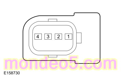 C543, pin 2, component side
|
|
C543, pin 3, component side
|
|
C634, pin 2, component side
|
|
C634, pin 3, component side
|
Is the resistance between 1 and 3 ohms?
| No
|
INSTALL a new front exterior handle.
REFER to:
Exterior Front Door Handle
(501-14 Handles, Locks, Latches and Entry Systems, Removal and Installation).
|
|
| W12
CHECK THE EXTERIOR DOOR HANDLE
|
-
Remove the opposite side exterior door handle.
-
For a front door,
REFER to:
Exterior Front Door Handle
(501-14 Handles, Locks, Latches and Entry Systems, Removal and Installation).
-
For a rear door,
REFER to:
Exterior Rear Door Handle
(501-14 Handles, Locks, Latches and Entry Systems, Removal and Installation).
-
Transfer the exterior door handle from the opposite side of the vehicle to the suspect exterior door. For example, if the
left front exterior door handle is suspect, transfer the right front exterior door handle to the left front door.
-
Operate the keyless entry feature from the suspect door.
Does the keyless entry feature operate from the suspect door?
| Yes
|
INSTALL a new exterior handle. For a front door,
REFER to:
Exterior Front Door Handle
(501-14 Handles, Locks, Latches and Entry Systems, Removal and Installation).
For a rear door,
REFER to:
Exterior Rear Door Handle
(501-14 Handles, Locks, Latches and Entry Systems, Removal and Installation).
|
| No
|
For a front door, GO to
W13
For a rear door, GO to
W16
|
|
| W13
CHECK THE EXTERIOR DOOR HANDLE ANTENNA CIRCUITS FOR A SHORT TO VOLTAGE
|
Is any voltage present?
|
| W14
CHECK THE EXTERIOR DOOR HANDLE ANTENNA CIRCUITS FOR A SHORT TO GROUND
|
Are the resistances greater than 10,000 ohms?
| No
|
REPAIR the affected circuit.
|
|
| W15
CHECK THE EXTERIOR DOOR HANDLE ANTENNA CIRCUITS FOR AN OPEN
|
Are the resistances less than 3 ohms?
| No
|
REPAIR the affected circuit.
|
|
| W16
CHECK FOR CORRECT BCM (BODY CONTROL MODULE)
OPERATION
|
-
Disconnect and inspect all the
connectors.
-
Repair:
-
corrosion (install new connectors or terminals - clean module pins)
-
damaged or bent pins - install new terminals pins
-
pushed-out pins - install new pins as necessary
-
Reconnect the
connectors and make sure they seat and latch correctly.
-
Operate the system and determine if the concern is still present.
Is the concern still present?
| Yes
|
CHECK
for any applicable Technical Service Bulletins (TSBs). If a
exists for this concern, DISCONTINUE this test and FOLLOW
instructions. If no Technical Service Bulletins (TSBs) address this concern, INSTALL a new
.
REFER to:
Body Control Module (BCM)
(419-10 Multifunction Electronic Modules, Removal and Installation).
|
| No
|
The system is operating correctly at this time. The concern may have been caused by module connections. ADDRESS the root cause
of any connector or pin issues.
|
|
The Luggage Compartment Lid Passive Entry Feature Is Inoperative
Refer to Wiring Diagrams Cell 117 for schematic and connector information.
Normal Operations and Fault Conditions
REFER to:
Handles, Locks, Latches and Entry Systems - System Operation and Component Description
(501-14 Handles, Locks, Latches and Entry Systems, Description and Operation).
Fault Trigger Conditions
|
|
Description
|
Fault Trigger Conditions
|
|
B10C7:01
|
Interior Trunk Antenna: General Electrical Failure
|
Sets when the
detects a fault from the keyless entry rear antenna input.
|
Possible Causes
-
Wiring, terminals or connectors
-
Keyless entry rear antenna
-
PINPOINT TEST X : THE LUGGAGE COMPARTMENT LID PASSIVE ENTRY FEATURE IS INOPERATIVE
| X1
CHECK THE LUGGAGE COMPARTMENT LID LATCH RELEASE OPERATION
|
-
Unlock the doors using the door lock control switch.
-
Press the luggage compartment lid release button located on the rear of the vehicle.
Does the luggage compartment lid latch release?
|
| X2
CHECK THE RKE (REMOTE KEYLESS ENTRY)
OPERATION
|
-
Close the luggage compartment lid.
-
Press the luggage compartment lid release button twice on a key.
Does the luggage compartment lid latch release?
|
| X3
CHECK THE KEYLESS ENTRY REAR ANTENNA
|
-
Disconnect Keyless Entry Rear Antenna C4082
.
-
Measure:
|
Positive Lead
|
Measurement / Action
|
Negative Lead
|
 C4082, pin 1, component side
|
|
C4082, pin 2, component side
|
Is the resistance between 1 and 3 ohms?
| No
|
INSTALL a new keyless entry rear antenna.
REFER to:
Keyless Entry Rear Antenna
(501-14 Handles, Locks, Latches and Entry Systems, Removal and Installation).
|
|
| X4
CHECK THE KEYLESS ENTRY REAR ANTENNA CIRCUITS FOR A SHORT TO VOLTAGE
|
-
Measure:
|
Positive Lead
|
Measurement / Action
|
Negative Lead
|
|
C2280E-16
|
|
Ground
|
|
C2280E-15
|
|
Ground
|
Is any voltage present?
| Yes
|
REPAIR the affected circuit.
|
|
| X5
CHECK THE KEYLESS ENTRY REAR ANTENNA CIRCUITS FOR A SHORT TO GROUND
|
-
Measure:
|
Positive Lead
|
Measurement / Action
|
Negative Lead
|
|
C2280E-16
|
|
Ground
|
|
C2280E-15
|
|
Ground
|
Are the resistances greater than 10,000 ohms?
| No
|
REPAIR the affected circuit.
|
|
| X6
CHECK THE KEYLESS ENTRY REAR ANTENNA CIRCUITS FOR AN OPEN
|
-
Measure:
|
Positive Lead
|
Measurement / Action
|
Negative Lead
|
|
C2280E-16
|
|
C4082-1
|
|
C2280E-15
|
|
C4082-2
|
Are the resistances less than 3 ohms?
| No
|
REPAIR the affected circuit.
|
|
| X7
CHECK FOR CORRECT BCM (BODY CONTROL MODULE)
OPERATION
|
-
Disconnect and inspect all the
connectors.
-
Repair:
-
corrosion (install new connectors or terminals - clean module pins)
-
damaged or bent pins - install new terminals pins
-
pushed-out pins - install new pins as necessary
-
Reconnect the
connectors and make sure they seat and latch correctly.
-
Operate the system and determine if the concern is still present.
Is the concern still present?
| Yes
|
CHECK
for any applicable Technical Service Bulletins (TSBs). If a
exists for this concern, DISCONTINUE this test and FOLLOW
instructions. If no Technical Service Bulletins (TSBs) address this concern, INSTALL a new
.
REFER to:
Body Control Module (BCM)
(419-10 Multifunction Electronic Modules, Removal and Installation).
|
| No
|
The system is operating correctly at this time. The concern may have been caused by module connections. ADDRESS the root cause
of any connector or pin issues.
|
|
U0146:00
Normal Operations and Fault Conditions
The
communicates with the
over the
. If the
does not receive messages from the
, features such as the keyless entry can be inoperative.
Fault Trigger Conditions
|
|
Description
|
Fault Trigger Conditions
|
|
U0146:00
|
Lost Communication With Gateway "A": No Sub Type Information
|
Sets when the
detects data messages are missing from the
over the
.
|
Possible Causes
-
Network communication concern
-
-
PINPOINT TEST Y : U0146:00
| Y1
VERIFY THE CUSTOMER CONCERN
|
-
Verify there is an observable symptom present.
Is an observable symptom present?
| No
|
The system is operating normally at this time. The
may have been set due to high network traffic or an intermittent fault condition.
|
|
| Y2
CHECK THE COMMUNICATION NETWORK
|
-
Using a diagnostic scan tool, perform a network test.
Does the
pass the network test?
| No
|
REFER to: Communications Network - 2.0L Duratec - Hybrid (96kW/130PS) (418-00 Module Communications Network)
.
|
|
| Y3
CHECK FOR CHARGING SYSTEM RELATED DIAGNOSTIC TROUBLE CODES (DTCS)
|
-
Using a diagnostic scan tool, retrieve all Continuous Memory Diagnostic Trouble Codes (CMDTCs).
Are any battery voltage related Diagnostic Trouble Codes (DTCs) retrieved?
| Yes
|
DIAGNOSE the charging system. Refer to the appropriate section in Group 303 for the procedure.
|
|
| Y4
RECHECK THE RTM (RADIO TRANSCEIVER MODULE)
DIAGNOSTIC TROUBLE CODES (DTCS)
|
|
NOTE:
If new modules were installed prior to the
being set, the module configuration may be incorrectly set during
or the
may not have been performed.
-
Using a diagnostic scan tool, clear the Diagnostic Trouble Codes (DTCs) and repeat the
self-test.
Is
U0146:00 still present?
| No
|
The system is operating correctly at this time. The
may have been set due to high network traffic or an intermittent fault condition.
|
|
| Y5
CHECK FOR DTC (DIAGNOSTIC TROUBLE CODE)
U0146 SET IN OTHER MODULES
|
-
Using a diagnostic scan tool, clear all Diagnostic Trouble Codes (DTCs).
-
Using a diagnostic scan tool, retrieve the Continuous Memory Diagnostic Trouble Codes (CMDTCs) from all modules.
Is
U0146 set in other modules?
| Yes
|
INSTALL a new
.
REFER to:
Gateway Module A (GWM)
(418-00 Module Communications Network, Removal and Installation).
|
|
U0258:87 or U1A00:00
Refer to Wiring Diagrams Cell 117 for schematic and connector information.
Normal Operation and Fault Conditions
The
communicates with the
over a
-based circuit and, when the network is awake, over the
.
Fault Trigger Conditions
|
|
Description
|
Fault Trigger Conditions
|
|
U1A00:00
|
Private Communication Network: No Sub Type Information
|
Sets when the
detects a fault with the
circuit to the
.
|
Fault Trigger Conditions
|
|
Description
|
Fault Trigger Conditions
|
|
U0258:87
|
Lost Communication With Radio Transceiver: Missing Message
|
Sets when the
detects a communication fault with the
over the
circuit.
|
Possible Causes
-
Wiring, terminals or connectors
-
-
PINPOINT TEST Z : U0258:87 OR U1A00:00
| Z1
CHECK IF THE RTM (RADIO TRANSCEIVER MODULE)
AND THE BCM (BODY CONTROL MODULE)
PASS THE NETWORK TEST
|
-
Using a diagnostic tool, perform the network test.
Does the
and the
pass the network test?
| No
|
REFER to: Communications Network - 2.0L Duratec - Hybrid (96kW/130PS) (418-00 Module Communications Network)
.
|
|
| Z2
CHECK THE LIN (LOCAL INTERCONNECT NETWORK)
CIRCUIT FOR A SHORT TO VOLTAGE
|
-
Measure:
|
Positive Lead
|
Measurement / Action
|
Negative Lead
|
|
C9026-2
|
|
Ground
|
Is any voltage present?
|
| Z3
CHECK THE LIN (LOCAL INTERCONNECT NETWORK)
CIRCUIT FOR A SHORT TO GROUND
|
-
Measure:
|
Positive Lead
|
Measurement / Action
|
Negative Lead
|
|
C9026-2
|
|
Ground
|
Is the resistance greater than 10,000 ohms?
|
| Z4
CHECK THE LIN (LOCAL INTERCONNECT NETWORK)
CIRCUIT FOR AN OPEN
|
-
Measure:
|
Positive Lead
|
Measurement / Action
|
Negative Lead
|
|
C9026-2
|
|
C2280G-26
|
Is the resistance less than 3 ohms?
|
| Z5
CHECK FOR CORRECT RTM (RADIO TRANSCEIVER MODULE)
OPERATION
|
-
Disconnect and inspect all the
connectors.
-
Repair:
-
corrosion (install new connectors or terminals - clean module pins)
-
damaged or bent pins - install new terminals pins
-
pushed-out pins - install new pins as necessary
-
Reconnect the
connectors and make sure they seat and latch correctly.
-
Operate the system and determine if the concern is still present.
Is the concern still present?
| Yes
|
CHECK
for any applicable Technical Service Bulletins (TSBs). If a
exists for this concern, DISCONTINUE this test and FOLLOW
instructions. If no Technical Service Bulletins (TSBs) address this concern, INSTALL a new
.
REFER to:
Radio Transceiver Module (RTM)
(419-10 Multifunction Electronic Modules, Removal and Installation).
TEST the system for normal operation. If the concern is still present, GO to
Z6
|
| No
|
The system is operating correctly at this time. The concern may have been caused by module connections. ADDRESS the root cause
of any connector or pin issues.
|
|
| Z6
CHECK FOR CORRECT BCM (BODY CONTROL MODULE)
OPERATION
|
-
Disconnect and inspect all the
connectors.
-
Repair:
-
corrosion (install new connectors or terminals - clean module pins)
-
damaged or bent pins - install new terminals pins
-
pushed-out pins - install new pins as necessary
-
Reconnect the
connectors and make sure they seat and latch correctly.
-
Operate the system and determine if the concern is still present.
Is the concern still present?
| Yes
|
CHECK
for any applicable Technical Service Bulletins (TSBs). If a
exists for this concern, DISCONTINUE this test and FOLLOW
instructions. If no Technical Service Bulletins (TSBs) address this concern, INSTALL a new
.
REFER to:
Body Control Module (BCM)
(419-10 Multifunction Electronic Modules, Removal and Installation).
|
| No
|
The system is operating correctly at this time. The concern may have been caused by module connections. ADDRESS the root cause
of any connector or pin issues.
|
|
P04B5, P04B9, or P04BA
Refer to Wiring Diagrams Cell 117 for schematic and connector information.
Normal Operation and Fault Conditions
The
monitors the fuel filler door ajar switch and sets a
if it detects a failure of the fuel filler door ajar input based on conditions after a refueling event.
Fault Trigger Conditions
|
|
Description
|
Fault Trigger Conditions
|
|
P04B5
|
Fuel Fill Door Stuck Open
|
Sets when the
detects the fuel filler door is open, the vehicle has been running for at least 5 minutes and the vehicle speed is greater
than 11 km/h (7 mph) (for example, the fuel filler door was not closed after a refueling event).
|
|
P04B9
|
Fuel Fill Door Position Sensor/Switch Circuit Low
|
Sets when the
detects the fuel filler door ajar switch input is short to ground. A fuel filler door that is never closed can cause this
to set.
|
|
P04BA
|
Fuel Fill Door Position Sensor/Switch Circuit High
|
Sets when the
detects the fuel filler door did not open when the
activated the fuel filler door release relay. An open circuit to the fuel filler door ajar switch can cause this
to set.
|
Possible Causes
-
Wiring, terminals or connectors
-
Fuel filler door ajar switch (part of the fuel filler door housing)
-
PINPOINT TEST AA : P04B5, P04B9, OR P04BA
| AA1
CHECK FOR MECHANICAL DAMAGE
|
-
Inspect fuel filler door for damage near the ajar switch.
Is any damage present?
| Yes
|
INSTALL a new fuel filler door housing.
|
|
| AA2
CHECK THE FUEL FILLER DOOR AJAR CIRCUITS FOR A SHORT TO VOLTAGE
|
-
Disconnect Fuel Filler Door Ajar Switch C3067
.
-
Measure:
|
Positive Lead
|
Measurement / Action
|
Negative Lead
|
|
C3067-1
|
|
Ground
|
|
C3067-2
|
|
Ground
|
|
C3067-3
|
|
Ground
|
Is any voltage present?
| Yes
|
REPAIR the affected circuit.
|
|
| AA3
CHECK THE FUEL FILLER DOOR AJAR CIRCUITS FOR A SHORT TO GROUND
|
-
Measure:
|
Positive Lead
|
Measurement / Action
|
Negative Lead
|
|
C3067-1
|
|
Ground
|
|
C3067-2
|
|
Ground
|
|
C3067-3
|
|
Ground
|
Are the resistances greater than 10,000 ohms?
| No
|
REPAIR the affected circuit.
|
|
| AA4
CHECK THE FUEL FILLER DOOR AJAR CIRCUITS FOR AN OPEN
|
-
Measure:
|
Positive Lead
|
Measurement / Action
|
Negative Lead
|
|
C3067-1
|
|
C175B-22
|
|
C3067-2
|
|
C175B-46
|
|
C3067-3
|
|
C175B-34
|
Are the resistances less than 3 ohms?
| Yes
|
INSTALL a new fuel filler door housing. CLEAR the Diagnostic Trouble Codes (DTCs) and repeat the self-test. If the concern
is still present, GO to
AA5
|
| No
|
REPAIR the affected circuit.
|
|
| AA5
CHECK FOR CORRECT PCM (POWERTRAIN CONTROL MODULE)
OPERATION
|
-
Disconnect and inspect all the
connectors.
-
Repair:
-
corrosion (install new connectors or terminals - clean module pins)
-
damaged or bent pins - install new terminals pins
-
pushed-out pins - install new pins as necessary
-
Reconnect the
connectors and make sure they seat and latch correctly.
-
Operate the system and determine if the concern is still present.
Is the concern still present?
| Yes
|
CHECK
for any applicable Technical Service Bulletins (TSBs). If a
exists for this concern, DISCONTINUE this test and FOLLOW
instructions. If no Technical Service Bulletins (TSBs) address this concern, INSTALL a new
. Refer to the appropriate section in Group 303 for the procedure.
|
| No
|
The system is operating correctly at this time. The concern may have been caused by module connections. ADDRESS the root cause
of any connector or pin issues.
|
|
B1087:83 or B1087:87
Refer to Wiring Diagrams Cell 117 for schematic and connector information.
Normal Operation and Fault Conditions
The
communicates with the Driver Rear Door Module (DRDM) over a
circuit. In the event the Driver Rear Door Module (DRDM) fails, the left rear power window and power door lock become inoperative.
The
communicates with the Passenger Rear Door Module (PRDM) over a
circuit. In the event the Passenger Rear Door Module (PRDM) fails, the right rear power window and power door lock become
inoperative.
/
Fault Trigger Conditions
|
|
Description
|
Fault Trigger Conditions
|
|
B1087:83
|
LIN Bus "A": Value Of Signal Protection Calculation Incorrect
|
Sets when the
/
detects a fault with the communication from the corresponding rear door moor module.
|
|
B1087:87
|
LIN Bus "A": Signal Invalid
|
Sets when the
/
detects a fault with the communication from the corresponding rear door moor module.
|
Possible Causes
-
Fuse
-
Wiring, terminals or connectors
-
Driver Rear Door Module (DRDM)
-
Passenger Rear Door Module (PRDM)
-
Visual Inspection and Diagnostic Pre-checks
-
Inspect the
fuse 29 (30A) (Driver Rear Door Module (DRDM)) and make sure it is OK.
-
Inspect the
fuse 30 (30A) (Passenger Rear Door Module (PRDM)) and make sure it is OK.
PINPOINT TEST AB : B1087:83 OR B1087:87
| AB1
CHECK IF THE DTC (DIAGNOSTIC TROUBLE CODE)
SET IN THE DDM (DRIVER DOOR MODULE)
|
-
Review the results from the
self-test.
Is
B1087:83 or B1087:87 set in the
?
|
| AB2
ISOLATE THE WINDOW CONTROL SWITCH
|
-
Disconnect Master Window Control Switch C535
.
-
Using a diagnostic scan tool, clear the Diagnostic Trouble Codes (DTCs) and repeat the self-test.
Is
B1087:83 or B1087:87 still present?
|
| AB3
CHECK FOR VOLTAGE TO THE REAR DOOR MODULE
|
-
Disconnect Driver Rear Door Module (DRDM) C728 (if
set in
).
-
Disconnect Passenger Rear Door Module (PRDM) C832 (if
set in
).
-
Measure:
Left Door
|
Positive Lead
|
Measurement / Action
|
Negative Lead
|
|
C728-1
|
|
Ground
|
Right Door
|
Positive Lead
|
Measurement / Action
|
Negative Lead
|
|
C832-1
|
|
Ground
|
Is the voltage greater than 11 volts?
| No
|
VERIFY the
fuse 29 (30A) (Driver Rear Door Module (DRDM)) or fuse 30 (30A) (Passenger Rear Door Module (PRDM)) is OK. If OK, GO to
AB4
If not OK, REFER to the Wiring Diagrams manual to identify the possible causes of the circuit short.
|
|
| AB4
CHECK THE REAR DOOR MODULE VOLTAGE SUPPLY CIRCUIT FOR AN OPEN
|
-
Measure:
Left Door
|
Positive Lead
|
Measurement / Action
|
Negative Lead
|
|
C728-1
|
|
C2280F-1
|
Right Door
|
Positive Lead
|
Measurement / Action
|
Negative Lead
|
|
C832-1
|
|
C2280F-9
|
Is the resistance less than 3 ohms?
|
| AB5
CHECK THE REAR DOOR MODULE GROUND CIRCUIT FOR AN OPEN
|
-
Measure:
Left Door
|
Positive Lead
|
Measurement / Action
|
Negative Lead
|
|
C728-2
|
|
Ground
|
Right Door
|
Positive Lead
|
Measurement / Action
|
Negative Lead
|
|
C832-2
|
|
Ground
|
Is the resistance less than 3 ohms?
|
| AB6
CHECK THE LIN (LOCAL INTERCONNECT NETWORK)
CIRCUIT FOR A SHORT TO VOLTAGE
|
-
Disconnect
C501A (if
set in
).
-
Disconnect
C652A (if
set in
).
-
Measure:
Left Door
|
Positive Lead
|
Measurement / Action
|
Negative Lead
|
|
C728-16
|
|
Ground
|
Right Door
|
Positive Lead
|
Measurement / Action
|
Negative Lead
|
|
C832-16
|
|
Ground
|
Is any voltage present?
|
| AB7
CHECK THE LIN (LOCAL INTERCONNECT NETWORK)
CIRCUIT FOR A SHORT TO GROUND
|
-
Measure:
Left Door
|
Positive Lead
|
Measurement / Action
|
Negative Lead
|
|
C728-16
|
|
Ground
|
Right Door
|
Positive Lead
|
Measurement / Action
|
Negative Lead
|
|
C832-16
|
|
Ground
|
Is the resistance greater than 10,000 ohms?
|
| AB8
CHECK THE CHECK THE LIN (LOCAL INTERCONNECT NETWORK)
CIRCUIT FOR AN OPEN
|
-
Measure:
Left Door
|
Positive Lead
|
Measurement / Action
|
Negative Lead
|
|
C728-16
|
|
C501A-5
|
Right Door
|
Positive Lead
|
Measurement / Action
|
Negative Lead
|
|
C832-16
|
|
C652A-5
|
Is the resistance less than 3 ohms?
|
| AB9
CHECK FOR CORRECT REAR DOOR MODULE OPERATION
|
-
Disconnect and inspect the Driver Rear Door Module (DRDM) or the Passenger Rear Door Module (PRDM) connector.
-
Repair:
-
corrosion (install new connectors or terminals - clean module pins)
-
damaged or bent pins - install new terminals pins
-
pushed-out pins - install new pins as necessary
-
Reconnect the Driver Rear Door Module (DRDM) or the Passenger Rear Door Module (PRDM) connector and make sure it seats and
latches correctly.
-
Operate the system and determine if the concern is still present.
Is the concern still present?
| Yes
|
CHECK
for any applicable Technical Service Bulletins (TSBs). If a
exists for this concern, DISCONTINUE this test and FOLLOW
instructions. If no Technical Service Bulletins (TSBs) address this concern, INSTALL a new Driver Rear Door Module (DRDM)
or the Passenger Rear Door Module (PRDM).
REFER to:
Rear Door Module (RDM)
(419-10 Multifunction Electronic Modules, Removal and Installation).
TEST the system for normal operation. If the concern is still present, GO to
AB10
|
| No
|
The system is operating correctly at this time. The concern may have been caused by module connections. ADDRESS the root cause
of any connector or pin issues.
|
|
| AB10
CHECK FOR CORRECT FRONT DOOR MODULE OPERATION
|
-
Disconnect and inspect all the
or
connectors.
-
Repair:
-
corrosion (install new connectors or terminals - clean module pins)
-
damaged or bent pins - install new terminals pins
-
pushed-out pins - install new pins as necessary
-
Reconnect the
or
connectors and make sure they seat and latch correctly.
-
Operate the system and determine if the concern is still present.
Is the concern still present?
| Yes
|
CHECK
for any applicable Technical Service Bulletins (TSBs). If a
exists for this concern, DISCONTINUE this test and FOLLOW
instructions. If no Technical Service Bulletins (TSBs) address this concern, INSTALL a new
or
. For a
,
REFER to:
Driver Door Module (DDM)
(419-10 Multifunction Electronic Modules, Removal and Installation).
For a
,
REFER to:
Passenger Door Module (PDM)
(419-10 Multifunction Electronic Modules, Removal and Installation).
|
| No
|
The system is operating correctly at this time. The concern may have been caused by module connections. ADDRESS the root cause
of any connector or pin issues.
|
|
| AB11
CHECK FOR CORRECT BCM (BODY CONTROL MODULE)
OPERATION
|
-
Disconnect and inspect all the
connectors.
-
Repair:
-
corrosion (install new connectors or terminals - clean module pins)
-
damaged or bent pins - install new terminals pins
-
pushed-out pins - install new pins as necessary
-
Reconnect the
connectors and make sure they seat and latch correctly.
-
Operate the system and determine if the concern is still present.
Is the concern still present?
| Yes
|
CHECK
for any applicable Technical Service Bulletins (TSBs). If a
exists for this concern, DISCONTINUE this test and FOLLOW
instructions. If no Technical Service Bulletins (TSBs) address this concern, INSTALL a new
.
REFER to:
Body Control Module (BCM)
(419-10 Multifunction Electronic Modules, Removal and Installation).
|
| No
|
The system is operating correctly at this time. The concern may have been caused by module connections. ADDRESS the root cause
of any connector or pin issues.
|
|
U0140:00
Normal Operation and Fault Conditions
The
/
communicates with the
over the
. If the
/
does not receive messages from the
, features such as the puddle lamps, exterior mirror turn signal and door switch illumination can be inoperative.
/
Fault Trigger Conditions
|
|
Description
|
Fault Trigger Conditions
|
|
U0140:00
|
Lost Communication With Body Control Module: No Sub-Type Information
|
Sets when the
/
detects data messages are missing from the
.
|
Possible Causes
-
Network communication concern
-
/
-
PINPOINT TEST AC : U0140:00
| AC1
VERIFY THE CUSTOMER CONCERN
|
-
Verify there is an observable symptom present.
Is an observable symptom present?
| No
|
The system is operating normally at this time. The
may have been set due to high network traffic or an intermittent fault condition.
|
|
| AC2
CHECK THE COMMUNICATION NETWORK
|
-
Using a diagnostic scan tool, perform a network test.
Does the
pass the network test?
| No
|
REFER to: Communications Network - 2.0L Duratec - Hybrid (96kW/130PS) (418-00 Module Communications Network)
.
|
|
| AC3
CHECK FOR BCM (BODY CONTROL MODULE)
DIAGNOSTIC TROUBLE CODES (DTCS)
|
-
Using a diagnostic scan tool, perform the
self-test.
Are any voltage related Diagnostic Trouble Codes (DTCs) present?
|
| AC4
RECHECK THE DDM (DRIVER DOOR MODULE)
OR PDM (PASSENGER DOOR MODULE)
DIAGNOSTIC TROUBLE CODES (DTCS)
|
|
NOTE:
If new modules were installed prior to the
being set, the module configuration may be incorrectly set during
or the
may not have been performed.
-
Using a diagnostic scan tool, clear the Diagnostic Trouble Codes (DTCs) and repeat the
/
self-test.
Is
U0140:00 still present?
| No
|
The system is operating correctly at this time. The
may have been set due to high network traffic or an intermittent fault condition.
|
|
| AC5
CHECK FOR DTC (DIAGNOSTIC TROUBLE CODE)
U0140 SET IN OTHER MODULES
|
-
Using a diagnostic scan tool, clear all Diagnostic Trouble Codes (DTCs).
-
Using a diagnostic scan tool, retrieve the Continuous Memory Diagnostic Trouble Codes (CMDTCs) from all modules.
Is
U0140 set in other modules?
|
U0208:00
Normal Operation and Fault Conditions
The
/
communicate with the
over the
. If the
/
does not receive messages from the
, features such as the memory mirror position can be inoperative.
/
Fault Trigger Conditions
|
|
Description
|
Fault Trigger Conditions
|
|
U0208:00
|
Lost Communication With "Seat Control Module A": No Sub-Type Information
|
Sets when the
/
detects data messages are missing from the
.
|
Possible Causes
-
Network communication concern
-
/
-
PINPOINT TEST AD : U0208:00
| AD1
VERIFY THE CUSTOMER CONCERN
|
-
Verify there is an observable symptom present.
Is an observable symptom present?
| No
|
The system is operating normally at this time. The
may have been set due to high network traffic or an intermittent fault condition.
|
|
| AD2
CHECK THE COMMUNICATION NETWORK
|
-
Using a diagnostic scan tool, perform a network test.
Does the
pass the network test?
| No
|
REFER to: Communications Network - 2.0L Duratec - Hybrid (96kW/130PS) (418-00 Module Communications Network)
.
|
|
| AD3
CHECK FOR DSM (DRIVER FRONT SEAT MODULE)
DIAGNOSTIC TROUBLE CODES (DTCS)
|
-
Using a diagnostic scan tool, perform the
self-test.
Are any voltage related Diagnostic Trouble Codes (DTCs) present?
| Yes
|
REFER to:
Front Seats
(501-10A Front Seats, Diagnosis and Testing).
|
|
| AD4
RECHECK THE DDM (DRIVER DOOR MODULE)
OR PDM (PASSENGER DOOR MODULE)
DIAGNOSTIC TROUBLE CODES (DTCS)
|
|
NOTE:
If new modules were installed prior to the
being set, the module configuration may be incorrectly set during
or the
may not have been performed.
-
Using a diagnostic scan tool, clear the Diagnostic Trouble Codes (DTCs) and repeat the
/
self-test.
Is
U0208:00 still present?
| No
|
The system is operating correctly at this time. The
may have been set due to high network traffic or an intermittent fault condition.
|
|
| AD5
CHECK FOR DTC (DIAGNOSTIC TROUBLE CODE)
U0208 SET IN OTHER MODULES
|
-
Using a diagnostic scan tool, clear all Diagnostic Trouble Codes (DTCs).
-
Using a diagnostic scan tool, retrieve the Continuous Memory Diagnostic Trouble Codes (CMDTCs) from all modules.
Is
U0208 set in other modules?
|
U0232:00
Normal Operation and Fault Conditions
The
communicates with the
over the
. If the
does not receive messages from the
, the side obstacle detection feature can be inoperative for the left side.
Fault Trigger Conditions
|
|
Description
|
Fault Trigger Conditions
|
|
U0232:00
|
Lost Communication With Side Obstacle Detection Control Module - Left: No Sub-Type Information
|
Sets when the
detects data messages are missing from the
.
|
Possible Causes
-
Network communication concern
-
-
PINPOINT TEST AE : U0232:00
| AE1
VERIFY THE CUSTOMER CONCERN
|
-
Verify there is an observable symptom present.
Is an observable symptom present?
| No
|
The system is operating normally at this time. The
may have been set due to high network traffic or an intermittent fault condition.
|
|
| AE2
CHECK THE COMMUNICATION NETWORK
|
-
Using a diagnostic scan tool, perform a network test.
Does the
pass the network test?
| No
|
REFER to: Communications Network - 2.0L Duratec - Hybrid (96kW/130PS) (418-00 Module Communications Network)
.
|
|
| AE3
CHECK FOR SODL (SIDE OBSTACLE DETECTION CONTROL MODULE LH)
DIAGNOSTIC TROUBLE CODES (DTCS)
|
-
Using a diagnostic scan tool, perform the
self-test.
Are any voltage related Diagnostic Trouble Codes (DTCs) present?
|
| AE4
RECHECK THE DDM (DRIVER DOOR MODULE)
DIAGNOSTIC TROUBLE CODES (DTCS)
|
|
NOTE:
If new modules were installed prior to the
being set, the module configuration may be incorrectly set during
or the
may not have been performed.
-
Using a diagnostic scan tool, clear the Diagnostic Trouble Codes (DTCs) and repeat the
self-test.
Is
U0232:00 still present?
| No
|
The system is operating correctly at this time. The
may have been set due to high network traffic or an intermittent fault condition.
|
|
| AE5
CHECK FOR DTC (DIAGNOSTIC TROUBLE CODE)
U0232 SET IN OTHER MODULES
|
-
Using a diagnostic scan tool, clear all Diagnostic Trouble Codes (DTCs).
-
Using a diagnostic scan tool, retrieve the Continuous Memory Diagnostic Trouble Codes (CMDTCs) from all modules.
Is
U0232 set in other modules?
| No
|
INSTALL a new
.
REFER to:
Driver Door Module (DDM)
(419-10 Multifunction Electronic Modules, Removal and Installation).
|
|
U0233:00
Normal Operation and Fault Conditions
The
communicates with the
over the
. If the
does not receive messages from the
, the side obstacle detection feature can be inoperative for the right side.
Fault Trigger Conditions
|
|
Description
|
Fault Trigger Conditions
|
|
U0233:00
|
Lost Communication With Side Obstacle Detection Control Module - Right: No Sub-Type Information
|
Sets when the
detects data messages are missing from the
.
|
Possible Causes
-
Network communication concern
-
-
PINPOINT TEST AF : U0233:00
| AF1
VERIFY THE CUSTOMER CONCERN
|
-
Verify there is an observable symptom present.
Is an observable symptom present?
| No
|
The system is operating normally at this time. The
may have been set due to high network traffic or an intermittent fault condition.
|
|
| AF2
CHECK THE COMMUNICATION NETWORK
|
-
Using a diagnostic scan tool, perform a network test.
Does the
pass the network test?
| No
|
REFER to: Communications Network - 2.0L Duratec - Hybrid (96kW/130PS) (418-00 Module Communications Network)
.
|
|
| AF3
CHECK FOR SODR (SIDE OBSTACLE DETECTION CONTROL MODULE RH)
DIAGNOSTIC TROUBLE CODES (DTCS)
|
-
Using a diagnostic scan tool, perform the
self-test.
Are any voltage related Diagnostic Trouble Codes (DTCs) present?
|
| AF4
RECHECK THE PDM (PASSENGER DOOR MODULE)
DIAGNOSTIC TROUBLE CODES (DTCS)
|
|
NOTE:
If new modules were installed prior to the
being set, the module configuration may be incorrectly set during
or the
may not have been performed.
-
Using a diagnostic scan tool, clear the Diagnostic Trouble Codes (DTCs) and repeat the
self-test.
Is
U0233:00 still present?
| No
|
The system is operating correctly at this time. The
may have been set due to high network traffic or an intermittent fault condition.
|
|
| AF5
CHECK FOR DTC (DIAGNOSTIC TROUBLE CODE)
U0233 SET IN OTHER MODULES
|
-
Using a diagnostic scan tool, clear all Diagnostic Trouble Codes (DTCs).
-
Using a diagnostic scan tool, retrieve the Continuous Memory Diagnostic Trouble Codes (CMDTCs) from all modules.
Is
U0233 set in other modules?
|
Copyright © Ford Motor Company