419-01C Passive Anti-Theft System (PATS) - Vehicles With: Push Button Start 2013 - 2014 Fusion
Diagnosis and Testing Procedure revision date: 07/31/2013

Passive Anti-Theft System (PATS)

BCM DTC Chart

Diagnostics in this manual assume a certain skill level and knowledge of Ford-specific diagnostic practices.
REFER to: Diagnostic Methods (100-00 General Information, Description and Operation).


  DTC Description Action
B11C6:01 Passenger Door External Antenna: General Electrical Failure   GO to Pinpoint Test A
B11CA:01 Driver Door External Antenna: General Electrical Failure   GO to Pinpoint Test A
B10C7:01 Interior Trunk Antenna: General Electrical Failure   GO to Pinpoint Test A
B10C8:01 Interior Centre Antenna: General Electrical Failure   GO to Pinpoint Test A
B10D7:05 PATS Key: System Programming Failure DIAGNOSE all other Diagnostic Trouble codes (DTCs) first. If no other Diagnostic Trouble codes (DTCs) are present, PROGRAM the suspect passive key again. If key programming fails, REPLACE the suspect passive key. PROGRAM the new passive key.
REFER to: Anti-Theft Security Access (419-01B Passive Anti-Theft System (PATS), General Procedures).
B10D8:00 PATS Key Less Than Minimum Programmed: No Sub Type Information Less than 2 keys are programmed (minimum of 2 keys must be programmed). PROGRAM the customer's second key.
REFER to: Anti-Theft Security Access (419-01B Passive Anti-Theft System (PATS), General Procedures).
B10DA:51 PATS Target Identifier: Not Programmed There is no PCM / SOBDMC ID stored in the BCM memory. PERFORM a parameter reset.
REFER to: Anti-Theft Security Access (419-01B Passive Anti-Theft System (PATS), General Procedures).
All other Diagnostic Trouble Codes (DTCs) -  
REFER to: Body Control Module (BCM) (419-10 Multifunction Electronic Modules, Diagnosis and Testing).


PCM / SOBDMC DTC Chart

Diagnostics in this manual assume a certain skill level and knowledge of Ford-specific diagnostic practices.
REFER to: Diagnostic Methods (100-00 General Information, Description and Operation).


  DTC Description Action
P161A Incorrect Response from Immobilizer Control Module The BCM ID received by the PCM / SOBDMC does not match the ID stored in the PCM / SOBDMC memory. PERFORM a parameter reset.
REFER to: Anti-Theft Security Access (419-01B Passive Anti-Theft System (PATS), General Procedures).
P161B Incorrect Response from Secondary Immobilizer Module The BCM ID received by the SOBDMC does not match the ID stored in the SOBDMC memory. PERFORM a parameter reset.
REFER to: Anti-Theft Security Access (419-01B Passive Anti-Theft System (PATS), General Procedures).
All other Diagnostic Trouble Codes (DTCs) -   Refer to Powertrain Control/Emissions Diagnosis (PC/ED) manual.


Symptom Chart

Symptom Chart: PATS

Diagnostics in this manual assume a certain skill level and knowledge of Ford-specific diagnostic practices.
REFER to: Diagnostic Methods (100-00 General Information, Description and Operation).


Condition Possible Sources Actions
The vehicle does not start with the passive key in certain areas within the vehicle but starts using the passive key backup location Refer to the Pinpoint Test   GO to Pinpoint Test A
Unable to turn the ignition on or the ready to drive indicator does not display Refer to the Pinpoint Test   GO to Pinpoint Test B
No Key Detected displays in the message center Refer to the Pinpoint Test   GO to Pinpoint Test C
Unable to program keys Refer to the Pinpoint Test   GO to Pinpoint Test A
The drive-away security feature is inoperative or does not operate correctly Refer to the Pinpoint Test   GO to Pinpoint Test D


Pinpoint Tests

The Vehicle Does Not Start With The Passive Key In Certain Areas Within The Vehicle But Starts Using The Passive Key Backup Location


Refer to Wiring Diagrams Cell 112 for schematic and connector information.

Normal Operation and Fault Conditions


REFER to: Passive Anti-Theft System (PATS) - System Operation and Component Description (419-01C Passive Anti-Theft System (PATS) - Vehicles With: Push Button Start, Description and Operation).


  BCM DTC Fault Trigger Conditions


  DTC Description Fault Trigger Conditions
B11C6:01 Passenger Door External Antenna: General Electrical Failure Sets when the BCM detects a fault with the passenger door keyless entry antenna.
B11CA:01 Driver Door External Antenna: General Electrical Failure Sets when the BCM detects a fault with the driver door keyless entry antenna.
B10C7:01 Interior Trunk Antenna: General Electrical Failure Sets when the BCM detects a fault with the keyless entry rear antenna.
B10C8:01 Interior Centre Antenna: General Electrical Failure Sets when the BCM detects a fault with the PATS center antenna.


Possible Sources


PINPOINT TEST A : THE VEHICLE DOES NOT START WITH THE PASSIVE KEY IN CERTAIN AREAS WITHIN THE VEHICLE BUT STARTS USING THE PASSIVE KEY BACKUP LOCATION
A1   CHECK THE PASSIVE KEY LOCATION
  • Check the location of the passive key. If it is placed in the far corners of the interior of the vehicle, move the passive key out of these areas and attempt to start the vehicle.

Does the vehicle start (ready to drive displays in the message center for hybrid vehicles)?

Yes The system is OK. INFORM the customer of the normal vehicle operation.
No GO to A2


A2   CHECK FOR ENVIRONMENTAL INTERFERENCE
  • Check for the use of a charger or other wireless device that can cause interference with the passive key. If any device is found, remove the device and attempt to start the vehicle.

Does the vehicle start (ready to drive displays in the message center for hybrid vehicles)?

Yes The system is OK. INFORM the customer of the normal vehicle operation.
No GO to A3


A3   CHECK THE SUSPECT ANTENNA

NOTE: For a concern with key programming or if unable to start the vehicle with the passive key in the back up slot, follow the diagnostics for the PATS center antenna.

  • Ignition ON.
  • Using a diagnostic scan tool, perform the BCM self-test. Record the DTC .
  • Ignition OFF.
  • Disconnect suspect antenna.
  • Measure:

      PATS Center Antenna ( DTC B10C8:01)


    Positive Lead Measurement / Action Negative Lead

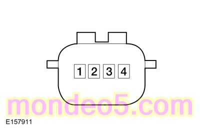
    C3513, pin 1, component side

    C3513, pin 2, component side


      Keyless Entry Rear Antenna ( DTC B10C7:01)


    Positive Lead Measurement / Action Negative Lead

    C4082, pin 1, component side

    C4082, pin 2, component side


      Driver Exterior Front Door Handle ( DTC B11CA:01)


    Positive Lead Measurement / Action Negative Lead

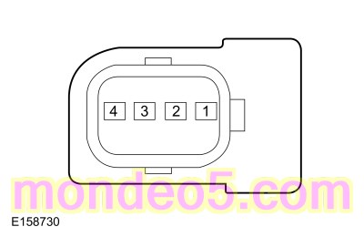
    C543, pin 2, component side

    C543, pin 3, component side


      Passenger Exterior Front Door Handle ( DTC B11C6:01)


    Positive Lead Measurement / Action Negative Lead

    C634, pin 2, component side

    C634, pin 3, component side


Is the resistance between 1 and 3 ohms?

Yes GO to A4
No INSTALL a new antenna in question. For the PATS center antenna,
REFER to: Passive Anti-Theft System (PATS) Center Antenna (419-01C Passive Anti-Theft System (PATS) - Vehicles With: Push Button Start, Removal and Installation).

For the keyless entry rear antenna,
REFER to: Keyless Entry Rear Antenna (501-14 Handles, Locks, Latches and Entry Systems, Removal and Installation).

For either front door exterior handle,
REFER to: Exterior Front Door Handle (501-14 Handles, Locks, Latches and Entry Systems, Removal and Installation).


A4   CHECK THE SUSPECT ANTENNA CIRCUITS FOR A SHORT TO VOLTAGE
  • Disconnect BCM C2280G (center PATS antenna).
  • Disconnect BCM C2280E (keyless entry rear antenna or exterior front door handle).
  • Measure:

      PATS Center Antenna


    Positive Lead Measurement / Action Negative Lead
      C3513-1   Ground
      C3513-2   Ground


      Keyless Entry Rear Antenna


    Positive Lead Measurement / Action Negative Lead
      C4082-1   Ground
      C4082-2   Ground


      Driver Exterior Front Door Handle


    Positive Lead Measurement / Action Negative Lead
      C543-2   Ground
      C543-3   Ground


      Passenger Exterior Front Door Handle


    Positive Lead Measurement / Action Negative Lead
      C634-2   Ground
      C634-3   Ground


Is any voltage present?

Yes REPAIR the affected circuit.
No GO to A5


A5   CHECK THE SUSPECT ANTENNA CIRCUITS FOR A SHORT TO GROUND
  • Measure:

      PATS Center Antenna


    Positive Lead Measurement / Action Negative Lead
      C3513-1   Ground
      C3513-2   Ground


      Keyless Entry Rear Antenna


    Positive Lead Measurement / Action Negative Lead
      C4082-1   Ground
      C4082-2   Ground


      Driver Exterior Front Door Handle


    Positive Lead Measurement / Action Negative Lead
      C543-2   Ground
      C543-3   Ground


      Passenger Exterior Front Door Handle


    Positive Lead Measurement / Action Negative Lead
      C634-2   Ground
      C634-3   Ground


Are the resistances greater than 10,000 ohms?

Yes GO to A6
No REPAIR the affected circuit.


A6   CHECK THE SUSPECT ANTENNA CIRCUITS FOR AN OPEN
  • Measure:

      PATS Center Antenna


    Positive Lead Measurement / Action Negative Lead
      C3513-1   C2280G-40
      C3513-2   C2280G-27


      Keyless Entry Rear Antenna


    Positive Lead Measurement / Action Negative Lead
      C4082-1   C2280E-16
      C4082-2   C2280E-15


      Driver Exterior Front Door Handle


    Positive Lead Measurement / Action Negative Lead
      C543-2   C2280E-13
      C543-3   C2280E-28


      Passenger Exterior Front Door Handle


    Positive Lead Measurement / Action Negative Lead
      C634-2   C2280E-12
      C634-3   C2280E-29


Are the resistances less than 3 ohms?

Yes INSTALL a new antenna in question. For the PATS center antenna, INSTALL a new PATS center antenna.
REFER to: Passive Anti-Theft System (PATS) Center Antenna (419-01C Passive Anti-Theft System (PATS) - Vehicles With: Push Button Start, Removal and Installation).

For the keyless entry rear antenna, INSTALL a new keyless entry rear antenna.
REFER to: Keyless Entry Rear Antenna (501-14 Handles, Locks, Latches and Entry Systems, Removal and Installation).

For either front door exterior handle,
REFER to: Exterior Front Door Handle (501-14 Handles, Locks, Latches and Entry Systems, Removal and Installation).

TEST the system for normal operation. If the concern is still present, GO to A7
No REPAIR the affected circuit.


A7   CHECK FOR CORRECT BCM (BODY CONTROL MODULE) OPERATION
  • Disconnect and inspect all of the BCM connectors.
  • Repair:
    • corrosion (install new connectors or terminals, clean module pins)
    • damaged or bent pins - install new terminals/pins
    • pushed-out pins - install new pins as necessary
  • Reconnect all the BCM connectors and make sure they seat and latch correctly.
  • Operate the system and determine if the concern is still present.

Is the concern still present?

Yes CHECK OASIS for any applicable Technical Service Bulletins (TSBs). If a TSB exists for this concern, DISCONTINUE this test and FOLLOW TSB instructions. If no Technical Service Bulletins (TSBs) address this concern, INSTALL a new BCM .
REFER to: Body Control Module (BCM) (419-10 Multifunction Electronic Modules, Removal and Installation).
No The system is operating correctly at this time. The concern may have been caused by module connections. Address the root cause of any connector or pin issues.


Unable To Turn The Ignition On Or The Ready To Drive Indicator Does Not Display

Normal Operation and Fault Conditions


REFER to: Passive Anti-Theft System (PATS) - System Operation and Component Description (419-01C Passive Anti-Theft System (PATS) - Vehicles With: Push Button Start, Description and Operation).

Possible Sources


PINPOINT TEST B : UNABLE TO TURN THE IGNITION ON OR THE READY TO DRIVE INDICATOR DOES NOT DISPLAY
B1   CHECK FOR THE NO KEY DETECTED MESSAGE
  • Check the message center while pressing the START/STOP button.

Is the No Key Detected message displayed in the message center?

Yes GO to Pinpoint Test C
No GO to B2


B2   CHECK THE IPC (INSTRUMENT PANEL CLUSTER) OPERATION
  • Observe the IPC operation while pressing the START/STOP button.

Do some of the indicators in the IPC prove-out, indicating the ignition is on?

Yes GO to B3
No GO to B4


B3   CHECK FOR BCM (BODY CONTROL MODULE) AND PCM (POWERTRAIN CONTROL MODULE) / SOBDMC (HYBRID POWERTRAIN CONTROL MODULE) DIAGNOSTIC TROUBLE CODES (DTCS)
  • Using a diagnostic scan tool, perform the BCM self-test.
  • Using a diagnostic scan tool, perform the PCM / SOBDMC self-test.

Are any BCM or PCM / SOBDMC Diagnostic Trouble Codes (DTCs) present?

Yes REFER to the BCM DTC Chart or the PCM / SOBDMC DTC Chart in this section.
No The condition is not PATS -related. DIAGNOSE the base drivetrain. Refer to Powertrain Control/Emissions Diagnosis (PC/ED) manual.


B4   CHECK FOR DIAGNOSTIC SCAN TOOL COMMUNICATION WITH THE VEHICLE
  • Follow the procedure to establish a diagnostic scan tool session with the vehicle.
    REFER to: Diagnostic Methods (100-00 General Information, Description and Operation).

Does the diagnostic scan tool establish communication with the vehicle?

Yes For hybrid vehicles, GO to B5
For non-hybrid vehicles, the no-start condition is not PATS -related. DIAGNOSE the accessories not having power when the ignition is on.
REFER to: Steering Wheel and Column Electrical Components (211-05 Steering Wheel and Column Electrical Components, Diagnosis and Testing).
No
REFER to: Communications Network (418-00 Module Communications Network, Diagnosis and Testing).


B5   CHECK FOR COMMUNICATION WITH THE IPC (INSTRUMENT PANEL CLUSTER)
  • Using a diagnostic scan tool, perform the network test.

Does the IPC pass the network test?

Yes GO to B6
No
REFER to: Communications Network (418-00 Module Communications Network, Diagnosis and Testing).


B6   CHECK FOR COMMUNICATION WITH THE BCM (BODY CONTROL MODULE)
  • Using a diagnostic scan tool, perform the network test.

Does the BCM pass the network test?

Yes The no-start condition is not PATS -related. DIAGNOSE the accessories not having power when the ignition is on.
REFER to: Steering Wheel and Column Electrical Components (211-05 Steering Wheel and Column Electrical Components, Diagnosis and Testing).
No
REFER to: Communications Network (418-00 Module Communications Network, Diagnosis and Testing).


No Key Detected Displays In The Message Center

Normal Operation and Fault Conditions


REFER to: Passive Anti-Theft System (PATS) - System Operation and Component Description (419-01C Passive Anti-Theft System (PATS) - Vehicles With: Push Button Start, Description and Operation).

Possible Sources

Visual Inspection and Diagnostic Pre-Checks


PINPOINT TEST C : NO KEY DETECTED DISPLAYS IN THE MESSAGE CENTER
C1   CHECK THE RKE (REMOTE KEYLESS ENTRY) TRANSMITTER OPERATION
  • Press the lock and unlock RKE transmitter buttons on the suspect passive key.

Do the doors lock and unlock?

Yes GO to C2
No
REFER to: Locks, Latches and Entry Systems (501-14 Handles, Locks, Latches and Entry Systems, Diagnosis and Testing).


C2   CHECK THE PASSIVE KEY OPERATION FROM MULTIPLE AREAS
  • Place the passive key in several locations within the vehicle and press the start/stop button each time.

Does the ignition turn on with the passive key in certain areas only?

Yes GO to Pinpoint Test A
No GO to C3


C3   CHECK FOR ENVIRONMENTAL INTERFERENCE
  • Check for the use of a charger or other wireless device that can cause interference with the passive key. If any device is found, remove the device and press the start/stop button.

Does the ignition turn on?

Yes INFORM the customer of the cause of the concern and the normal operation of the vehicle.
No GO to C4


C4   CHECK THE PASSIVE KEY
  • Place the passive key in the backup location and press the start/stop button.

Does the ignition turn on?

Yes GO to Pinpoint Test A
No GO to C5


C5   CHECK THE PASSIVE KEY PROGRAMMING

Does the passive key successfully program?

Yes The concern was caused by an unprogrammed passive key.
No GO to Pinpoint Test A


The Drive-Away Security Feature Is Inoperative Or Does Not Operate Correctly

Normal Operation and Fault Conditions


REFER to: Passive Anti-Theft System (PATS) - System Operation and Component Description (419-01C Passive Anti-Theft System (PATS) - Vehicles With: Push Button Start, Description and Operation).

Possible Sources


PINPOINT TEST D : THE DRIVE-AWAY SECURITY FEATURE IS INOPERATIVE OR DOES NOT OPERATE CORRECTLY
D1   CHECK THE PASSIVE KEY OPERATION
  • With a valid programmed passive key in the vehicle, apply the brake pedal and press the START/STOP button.

Does the vehicle start?

Yes GO to D2
No REFER to the Symptom Chart: PATS to correctly diagnose the symptom


D2   CHECK THE BRAKE SHIFT INTERLOCK OPERATION
  • While applying the brake pedal, place the transmission out of PARK.

Does the transmission shift out of PARK?

Yes The system is operating correctly. The concern may have been caused by environmental interference of the passive key or PATS antenna.
No DIAGNOSE the brake shift interlock system. Refer to the appropriate section in Group 307 for the procedure.