| 414-00 Charging System - General Information
|
2013 - 2014 Fusion
|
| Diagnosis and Testing
|
Procedure revision date:
07/16/2013
|
Charging System
Inspection and Verification
Diagnostics in this manual assume a certain skill level and knowledge of Ford-specific diagnostic practices.
REFER to:
Diagnostic Methods
(100-00 General Information, Description and Operation).
for information about these practices.
-
Verify the customer concern by operating the starting system.
-
Check the battery condition and state of charge.
REFER to:
Battery
(414-01 Battery, Mounting and Cables, Diagnosis and Testing).
-
Before diagnosing or repairing the charging system inspect the following items:
-
Fusible links
-
Abnormal ignition-off current drain(s).
REFER to:
Battery Drain Check
(414-01 Battery, Mounting and Cables, General Procedures).
-
High current
for loose or corroded connections
-
Wiring, terminals or connectors
-
If an obvious cause for an observed or reported concern is found, correct the cause (if possible) before proceeding.
DTC Charts
Diagnostics in this manual assume a certain skill level and knowledge of Ford-specific diagnostic practices.
REFER to:
Diagnostic Methods
(100-00 General Information, Description and Operation).
for information about these practices.
PCM DTC Chart
|
DTC
|
Description
|
Action
|
|
P0562
|
System Voltage Low
|
GO to Pinpoint Test B
|
|
P0563
|
System Voltage High
|
GO to Pinpoint Test A
|
|
P0620
|
Generator Control Circuit
|
GO to Pinpoint Test H
|
|
P0625
|
Generator Field Terminal Circuit Low
|
GO to Pinpoint Test I
|
|
P0626
|
Generator Field Terminal Circuit High
|
GO to Pinpoint Test I
|
|
P065B
|
Generator Control Circuit Range/performance
|
REPLACE the generator.
REFER to:
Generator - 1.5L EcoBoost (118kW/160PS)
(414-02 Generator and Regulator, Removal and Installation).
|
|
P0A5A
|
Generator Current Sensor Circuit Range/Performance
|
GO to Pinpoint Test G
|
|
P0A5B
|
Generator Current Sensor Circuit Low
|
GO to Pinpoint Test G
|
|
P0A5C
|
Generator Current Sensor Circuit High
|
GO to Pinpoint Test G
|
|
P1397
|
System Voltage Out Of Self-Test Range
|
If combined with P0562,
GO to Pinpoint Test B
If combined with P0563,
GO to Pinpoint Test A
|
|
All Other DTCs
|
—
|
For 1.5L EcoBoost,
REFER to:
Electronic Engine Controls
(303-14A Electronic Engine Controls - 1.5L EcoBoost (118kW/160PS), Diagnosis and Testing).
For 1.6L EcoBoost, REFER to:
Electronic Engine Controls
(303-14B Electronic Engine Controls - 1.6L EcoBoost (132kW/180PS) - Sigma, Diagnosis and Testing).
For 2.0L EcoBoost, REFER to:
Electronic Engine Controls
(303-14C Electronic Engine Controls - 2.0L EcoBoost (184kW/250PS) - MI4, Diagnosis and Testing).
For 2.5L Duratec, REFER to:
Electronic Engine Controls
(303-14D Electronic Engine Controls - 2.5L Duratec (125kW/170PS), Diagnosis and Testing).
|
BCM DTC Chart
|
DTC
|
Description
|
Action
|
|
B11DB:02
|
Battery Monitoring Module "A", General Signal Failure
|
GO to Pinpoint Test F
|
|
B11DB:08
|
Battery Monitoring Module "A", Bus Signal / Message Failure
|
GO to Pinpoint Test F
|
|
B11DB:11
|
Battery Monitoring Module "A", Circuit Short To Ground
|
GO to Pinpoint Test F
|
|
B11DB:49
|
Battery Monitoring Module "A", Internal Electronic Failure
|
CLEAR the Diagnostic Trouble Codes (DTCs). REPEAT the
self test. If Diagnostic Trouble Codes (DTCs) B11DB:49 is retrieved, INSTALL new Battery Monitoring Sensor.
REFER to:
Battery Monitoring Sensor
(414-01 Battery, Mounting and Cables, Removal and Installation).
|
|
B11DB:55
|
Battery Monitoring Module "A", Not Configured
|
CHECK the vehicle service history for recent service actions related to this module. This
sets due to incomplete or incorrect
prodedures. INSTALL As-Built data from Professional Technician Society (PTS) following diagnostic scan tool instructions
under Module Programming>As-Built.
|
|
B11DB:9A
|
Battery Monitoring Module "A", Component or System Operating Conditions
|
GO to Pinpoint Test F
|
|
B130C:12
|
Load Shed Control Circuit Short To Battery
|
GO to Pinpoint Test E
|
|
B130C:14
|
Load Shed Control Circuit Short To Ground or Open
|
GO to Pinpoint Test E
|
|
B1438:03
|
Battery Current Sensor,
/
Failure
|
GO to Pinpoint Test E
|
|
U1007:31
|
Lost Communication With Battery Monitoring Sensor "A": No Signal
|
GO to Pinpoint Test F
|
|
All Other DTCs
|
—
|
REFER to:
Body Control Module (BCM)
(419-10 Multifunction Electronic Modules, Diagnosis and Testing).
|
Symptom Chart(s)
Symptom Chart: Charging System
Diagnostics in this manual assume a certain skill level and knowledge of Ford-specific diagnostic practices.
REFER to:
Diagnostic Methods
(100-00 General Information, Description and Operation).
for information about these practices.
Symptom Chart
|
Condition
|
Possible Sources
|
Actions
|
|
System voltage high
|
Refer to the Pinpoint Test
|
GO to Pinpoint Test A
|
|
System voltage low or battery is discharged
|
Refer to the Pinpoint Test
|
GO to Pinpoint Test B
|
|
The generator is noisy
|
Refer to the Pinpoint Test
|
GO to Pinpoint Test C
|
|
Radio interference
|
Refer to the Pinpoint Test
|
GO to Pinpoint Test D
|
|
Charging system warning indicator is never or always on
|
-
Wiring, terminals or connectors
-
-
Generator
-
|
RETRIEVE Diagnostic Trouble Codes (DTCs) from all modules. If any Diagnostic Trouble Codes (DTCs) are found, Refer to DTC
Chart in this section. If no Diagnostic Trouble Codes (DTCs) are found,
REFER to:
Instrumentation, Message Center and Warning Chimes
(413-01 Instrumentation, Message Center and Warning Chimes, Diagnosis and Testing).
|
Pinpoint Tests
System Voltage High
Refer to Wiring Diagrams Cell 12 for schematic and connector information.
NOTE:
Diagnostic Trouble Code (
) P0563 can be set if the vehicle has been recently jump started or the battery has been recently charged. The battery may
become discharged due to excessive load(s) on the charging system from aftermarket accessories or if vehicle accessories have
been operating for an extended period of time without the engine running.
Normal Operation and Fault Conditions
With the engine running, the charging system supplies voltage to the battery and the vehicle electrical system through the
high current
and battery B+ cable. The voltage that is supplied to the vehicle electrical system is used for the operation of the various
vehicle systems and modules. Many modules monitor this voltage and if it rises above or below their calibrated setpoints,
a
sets.
Diagnostic Trouble Code (DTC) Fault Trigger Conditions
|
DTC
|
Description
|
Fault Trigger Conditions
|
|
P0563
|
System Voltage High
|
This
sets in the
when the
detects voltage from the charging system greater than 15.9 volts with vehicle speed above 8 km/h (5 mph).
|
|
P1397
|
System Voltage Out of Self-Test Range
|
If the voltage rises above or drops below the calibrated set point, the
sets this
. This
may also be set if the vehicle has been recently jump started or has had a discharged battery.
|
Possible Sources
-
Battery
-
Generator
-
Engine, generator or battery ground
-
-
Wiring, terminals or connectors
Visual Inspection and Diagnostic Pre-checks
-
Inspect the high current
for loose or corroded connections.
PINPOINT TEST A : SYSTEM VOLTAGE HIGH
| NOTE:
Make sure battery voltage is greater than 12.2 volts prior to and during this pinpoint test.
|
| NOTE:
Do not have a battery charger attached during vehicle testing.
|
| A1
CHECK THE BATTERY CONDITION
|
-
Check the battery condition and state of charge.
REFER to:
Battery
(414-01 Battery, Mounting and Cables, Diagnosis and Testing).
Does the battery pass the condition test?
| No
|
CHARGE or INSTALL a new battery as necessary.
REFER to:
Battery
(414-01 Battery, Mounting and Cables, Removal and Installation).
|
|
| A2
RETRIEVE THE PCM (POWERTRAIN CONTROL MODULE)
DIAGNOSTIC TROUBLE CODES (DTCS)
|
-
Using a diagnostic scan tool, perform the
self-test.
Is
P0620, P0625 or P0626 present?
|
| A3
MONITOR THE GENERATOR VOLTAGE DESIRED (GENVDSD) PID (PARAMETER IDENTIFICATION)
|
-
Using a diagnostic scan tool, view the
Parameter Identifications (PIDs).
Does the
indicate 15.9 volts or less?
|
| A4
COMPARE THE GENERATOR VOLTAGE DESIRED (GENVDSD) PID (PARAMETER IDENTIFICATION)
WITH BATTERY VOLTAGE
|
-
With the engine still running at idle, measure and record:
|
Positive Lead
|
Measurement / Action
|
Negative Lead
|
|

|
|
-
Using a diagnostic scan tool, view the
GENVDSD.
Is the recorded battery voltage within ±0.5 volt of the
?
| Yes
|
The system is operating correctly at this time. The concern may have been caused by an intermittently loose or corroded connector.
ADDRESS the root cause of any connector or pin issues.
|
|
| A5
MEASURE THE "A" SENSE VOLTAGE
|
-
Disconnect Generator C1558A (2.0L EcoBoost).
-
Disconnect Generator C102A (All other engines).
-
Measure and record:
|
Positive Lead
|
Measurement / Action
|
Negative Lead
|
|
|
|
|
-
For the 2.0L EcoBoost, measure:
|
Positive Lead
|
Measurement / Action
|
Negative Lead
|
|
C1558A-3
|
|
Ground
|
-
For all other engines, measure:
|
Positive Lead
|
Measurement / Action
|
Negative Lead
|
|
C102A-3
|
|
Ground
|
Is the "A" sense voltage equal to the recorded battery voltage?
| No
|
VERIFY high current
fuse 46 (10A) is OK. If OK, REPAIR the circuit. If not OK, REFER to the Wiring Diagrams manual to identify the possible causes
of the circuit short.
|
|
| A6
"A" SENSE CIRCUIT LOAD TEST
|
|
NOTICE:
The following step uses a test light to simulate normal circuit loads. Use only the test light recommended in the Special
Tools table at the beginning of this section. To avoid connector terminal damage, use the Flex Probe Kit for the test light
probe connection to the vehicle. Do not use the test light probe directly on any connector.
NOTE:
This step puts a load on the "A" sense circuit. If there are corroded or loose connections, loading the circuit may help show
the fault. A 250-350 mA incandescent 12-volt test lamp is required for this step. This circuit cannot be loaded correctly
using an LED-style test lamp.
-
For the 2.0L EcoBoost, connect:
|
Positive Lead
|
Measurement / Action
|
Negative Lead
|
|
C1558A-3
|

|
Ground
|
-
For all other engines, connect:
|
Positive Lead
|
Measurement / Action
|
Negative Lead
|
|
C102A-3
|
|
Ground
|
Does the test lamp illuminate?
|
| A7
CHECK THE VOLTAGE DROP IN THE VEHICLE GROUNDS
|
-
Connect Generator C1558A (2.0L EcoBoost).
-
Connect Generator C102A (For all other engines).
-
With the engine still running at idle, headlamps on and heater blower on high, measure:
Is the voltage drop less than 0.5 volt?
| No
|
INSPECT and REPAIR the engine ground, generator ground or the battery ground for corrosion.
|
|
| A8
CHECK THE GENERATOR OUTPUT
|
-
Increase the engine rpm until the generator starts to generate output.
-
With the engine running, measure and record:
|
Positive Lead
|
Measurement / Action
|
Negative Lead
|
|
|
|
Ground
|
Is the voltage above 15.2 volts?
|
| A9
MONITOR THE GENERATOR COMMAND (GENCMD), GENERATOR MONITOR (GENMON) AND GENERATOR VOLTAGE DESIRED (GENVDSD) PIDS
|
-
Disconnect Generator C1558A (2.0L EcoBoost).
-
Disconnect Generator C102A (All other engines).
-
For the 2.0L EcoBoost, connect:
|
Positive Lead
|
Measurement / Action
|
Negative Lead
|
|
C1558A-1
|

|
C1558A-2
|
-
For all other engines, connect:
|
Positive Lead
|
Measurement / Action
|
Negative Lead
|
|
C102A-1
|
|
C102A-2
|
-
Using a diagnostic scan tool, view
Parameter Identifications (PIDs).
-
Using the active command, set the
GENVDSD to 14 volts.
-
Monitor the
Parameter Identifications (PIDs) GENMON and GENVDSD.
Do the Parameter Identifications (PIDs) read within 5% of each other?
|
| A10
COMPARE THE SUPPLY VOLTAGE (VPWR) PID (PARAMETER IDENTIFICATION)
TO BATTERY VOLTAGE
|
-
With the engine still running at idle, measure and record:
|
Positive Lead
|
Measurement / Action
|
Negative Lead
|
|
|
|
|
-
Using a diagnostic scan tool, view
Parameter Identifications (PIDs).
Does the
accurately display battery voltage within ±0.5 volt of the recorded battery voltage?
|
| A11
CHECK PCM (POWERTRAIN CONTROL MODULE)
SUPPLY VOLTAGE CIRCUITS
|
-
Remove the fused jumper wire.
-
Disconnect
C1915B (1.5L EcoBoost).
-
Disconnect
C1232B (1.6L EcoBoost).
-
Disconnect
C1381B (2.0L EcoBoost).
-
Disconnect
C1551B (2.5L Duratec).
-
For the 1.5L EcoBoost, measure:
-
For the 1.6L EcoBoost, measure:
-
For the 2.0L EcoBoost, measure:
-
For the 2.5L Duratec, measure:
Are the resistances less than 3 ohm?
| No
|
REPAIR the affected circuit(s).
|
|
| A12
CHECK FOR CORRECT PCM (POWERTRAIN CONTROL MODULE)
OPERATION
|
-
Disconnect and inspect all
connectors.
-
Repair:
-
corrosion (install new connector or terminals – clean module pins)
-
damaged or bent pins – install new terminals/pins
-
pushed-out pins – install new pins as necessary
-
Reconnect the
connectors. Make sure they seat and latch correctly.
-
Operate the system and determine if the concern is still present.
Is the concern still present?
| Yes
|
CHECK
for any applicable Technical Service Bulletins (TSBs). If a
exists for this concern, DISCONTINUE this test and FOLLOW the
instructions. If no Technical Service Bulletins (TSBs) address this concern, INSTALL a new
. For 1.5L EcoBoost,
REFER to:
Powertrain Control Module (PCM)
(303-14A Electronic Engine Controls - 1.5L EcoBoost (118kW/160PS), Removal and Installation).
For 1.6L EcoBoost, REFER to:
Powertrain Control Module (PCM)
(303-14B Electronic Engine Controls - 1.6L EcoBoost (132kW/180PS) - Sigma, Removal and Installation).
For 2.0L EcoBoost, REFER to:
Powertrain Control Module (PCM)
(303-14C Electronic Engine Controls - 2.0L EcoBoost (184kW/250PS) - MI4, Removal and Installation).
For 2.5L Duratec REFER to:
Powertrain Control Module (PCM)
(303-14D Electronic Engine Controls - 2.5L Duratec (125kW/170PS), Removal and Installation).
CLEAR all Diagnostic Trouble Codes (DTCs) in all modules.
|
| No
|
The system is operating correctly at this time. The concern may have been caused by module connections. ADDRESS the root cause
of any connector or pin issues.
|
|
System Voltage Low or Battery is Discharged
Refer to Wiring Diagrams Cell 12 for schematic and connector information.
Normal Operation and Fault Conditions
With the engine running, the charging system supplies voltage to the battery and the vehicle electrical system through the
high current
and battery B+ cable. The
monitors this B+ voltage through its own voltage supply circuit.
Diagnostic Trouble Code (DTC) Fault Trigger Conditions
|
DTC
|
Description
|
Fault Trigger Conditions
|
|
P0562
|
System Voltage Low
|
If voltage drops 1.5 volts or more below the generator voltage desired (calculated by the
), this
sets after 30 seconds.
|
|
P1397
|
System Voltage Out of Self-Test Range
|
If the voltage rises above or drops below the calibrated set point, the
sets this
. This
may also be set if the vehicle has been recently jump started or has had a discharged battery.
|
Possible Sources
-
Battery
-
Fuses or fusible links
-
Generator
-
-
High current
-
Wiring, terminals or connectors
Visual Inspection and Diagnostic Pre-checks
-
Inspect for abnormal ignition-off current drain(s).
-
Inspect the battery.
-
Inspect the high current
for loose or corroded connections.
-
Inspect the generator clutch.
PINPOINT TEST B : SYSTEM VOLTAGE LOW OR BATTERY IS DISCHARGED
| NOTE:
Make sure battery voltage is greater than 12.2 volts prior to and during this pinpoint test.
|
| NOTE:
Do not have a battery charger attached during vehicle testing.
|
| B1
CHECK THE BATTERY CONDITION
|
-
Check the battery condition and state of charge.
REFER to:
Battery
(414-01 Battery, Mounting and Cables, Diagnosis and Testing).
Does the battery pass the condition test?
| No
|
CHARGE or INSTALL a new battery as necessary.
REFER to:
Battery
(414-01 Battery, Mounting and Cables, Removal and Installation).
|
|
| B2
RETRIEVE DIAGNOSTIC TROUBLE CODES (DTCS)
|
-
Using a diagnostic scan tool, perform the
self-test.
Is
P0620, P0625 or P0626 present?
|
| B3
CHECK THE GENERATOR CONNECTIONS
|
-
Disconnect all of the generator connectors and inspect for:
-
corrosion (install new connector or terminals – clean module pins)
-
damaged or bent pins – install new terminals/pins
-
pushed-out pins – install new pins as necessary
-
Reconnect the generator connectors. Make sure they seat and latch correctly.
-
Measure and record:
|
Positive Lead
|
Measurement / Action
|
Negative Lead
|
|
|
|
|
-
For the 2.0L EcoBoost, measure:
|
Positive Lead
|
Measurement / Action
|
Negative Lead
|
|
C1558C-1
|
|
Ground
|
-
For all other engines, measure:
|
Positive Lead
|
Measurement / Action
|
Negative Lead
|
|
C102C-1
|
|
Ground
|
Is the voltage within 0.5 volt of the recorded battery voltage?
|
| B4
CHECK THE VOLTAGE DROP IN THE GENERATOR B+ CIRCUIT
|
-
For the 2.0L EcoBoost, with the engine running at idle, headlamps on and blower on high, measure:
|
Positive Lead
|
Measurement / Action
|
Negative Lead
|
|
C1558C-1
|
|
|
-
For all other engines, with the engine running at idle, headlamps on and blower on high, measure:
|
Positive Lead
|
Measurement / Action
|
Negative Lead
|
|
C102C-1
|
|
|
-
Perform a wiggle test of the generator wiring and connections while measuring voltage drop.
Is the voltage drop less than 0.5 volt?
| No
|
INSPECT and REPAIR any corrosion in the generator B+ circuit or positive battery cable connections.
|
|
| B5
CHECK THE VOLTAGE DROP IN THE VEHICLE GROUNDS
|
-
With the engine still running at idle, headlamps on and heater blower on high, measure:
Is the voltage drop less than 0.5 volt?
| No
|
INSPECT and REPAIR the engine ground, generator ground or the battery ground for corrosion.
|
|
| B6
MONITOR THE GENERATOR VOLTAGE DESIRED (GENVDSD) PID (PARAMETER IDENTIFICATION)
WHILE COMMANDED
|
-
Using a diagnostic scan tool, view the
GENVDSD
.
-
Using a diagnostic scan tool active command, set the
GENVDSD to 14 volts.
-
With the engine still running at idle, measure battery and record:
|
Positive Lead
|
Measurement / Action
|
Negative Lead
|
|
|
|
|
Is the recorded battery voltage within ±0.5 volt of the
?
|
| B7
COMPARE THE SUPPLY VOLTAGE (VPWR) PID (PARAMETER IDENTIFICATION)
TO BATTERY VOLTAGE
|
-
With the engine still running at idle, headlamps on and blower on high, measure and record:
|
Positive Lead
|
Measurement / Action
|
Negative Lead
|
|
|
|
|
-
Using a diagnostic scan tool, view the
VPWR.
Does the
accurately display battery voltage within ±0.5 volt of the recorded battery voltage?
| No
|
REPAIR high resistance or loose connections in the affected
power circuit(s).
|
|
| B8
CHECK PCM (POWERTRAIN CONTROL MODULE)
GROUND FOR HIGH RESISTANCE
|
-
Using a diagnostic scan tool, view
VPWR and record.
-
With the engine still running at idle, turn headlamps on and blower on high.
-
Measure and record:
|
Positive Lead
|
Measurement / Action
|
Negative Lead
|
|
|
|
|
-
Using a diagnostic scan tool, view
VPWR and record.
Does the
read within ±0.5 volt of battery voltage with accessory loads on and off?
| No
|
REPAIR the affected
ground circuit(s).
|
|
| B9
MONITOR THE SUPPLY VOLTAGE (VPWR) PID (PARAMETER IDENTIFICATION)
|
-
NOTE:
Measure battery voltage at the battery.
With the engine still running at idle, turn off all accessory loads.
-
Measure and record:
|
Positive Lead
|
Measurement / Action
|
Negative Lead
|
|
|
|
|
-
Using a diagnostic scan tool, view
VPWR and record.
-
Momentarily accelerate the engine to Wide Open Throttle (WOT) and release. Repeat this step 4-5 times while continuing to
monitor the
.
Does the
stay within 0.5 volt of the recorded battery voltage when the engine Revolutions Per Minute (RPM) are increased?
| Yes
|
The system is operating correctly at this time. The concern may have been caused by a loose or corroded connector. INSPECT
and REPAIR any connector or pin issues found. If no connector or pin issues are found, Perform the battery drain test.
REFER to:
Battery Drain Check
(414-01 Battery, Mounting and Cables, General Procedures).
|
|
| B10
CHECK GENERATOR CLUTCH OPERATION
|
-
Perform the generator clutch component test in this section.
Is the generator clutch OK?
|
| B11
CHECK FOR CORRECT PCM (POWERTRAIN CONTROL MODULE)
OPERATION
|
-
Disconnect and inspect all
connectors.
-
Repair:
-
corrosion (install new connector or terminals – clean module pins)
-
damaged or bent pins – install new terminals/pins
-
pushed-out pins – install new pins as necessary
-
Reconnect the
connectors. Make sure they seat and latch correctly.
-
Operate the system and determine if the concern is still present.
Is the concern still present?
| Yes
|
CHECK
for any applicable Technical Service Bulletins (TSBs). If a
exists for this concern, DISCONTINUE this test and FOLLOW the
instructions. If no Technical Service Bulletins (TSBs) address this concern, INSTALL a new
. For 1.5L EcoBoost,
REFER to:
Powertrain Control Module (PCM)
(303-14A Electronic Engine Controls - 1.5L EcoBoost (118kW/160PS), Removal and Installation).
For 1.6L EcoBoost, REFER to:
Powertrain Control Module (PCM)
(303-14B Electronic Engine Controls - 1.6L EcoBoost (132kW/180PS) - Sigma, Removal and Installation).
For 2.0L EcoBoost, REFER to:
Powertrain Control Module (PCM)
(303-14C Electronic Engine Controls - 2.0L EcoBoost (184kW/250PS) - MI4, Removal and Installation).
For 2.5L Duratec REFER to:
Powertrain Control Module (PCM)
(303-14D Electronic Engine Controls - 2.5L Duratec (125kW/170PS), Removal and Installation).
CLEAR all Diagnostic Trouble Codes (DTCs) in all modules.
|
| No
|
The system is operating correctly at this time. The concern may have been caused by a loose or corroded connector. ADDRESS
the root cause of any connector or pin issues.
|
|
The Generator is Noisy
Normal Operation and Fault Conditions
The generator is belt-driven by the engine accessory drive system. There are several sources of generator noise which include
bearing noise, electrical fault noise, generator or belt pulley misalignment. A generator with certain types of diode or stator
failures can also produce an audible noise.
Possible Sources
-
belt
-
Loose bolts/brackets
-
Generator/pulleys
Visual Inspection and Diagnostic Pre-checks
-
Inspect the
belt.
-
Inspect for loose bolts/brackets.
-
Inspect the generator/pulley.
PINPOINT TEST C : THE GENERATOR IS NOISY
| C1
CHECK FOR ACCESSORY DRIVE BELT NOISE AND LOOSE MOUNTING BRACKETS
|
-
Check the
belt and tensioner for damage and correct installation. For 1.5L EcoBoost,
REFER to:
Accessory Drive
(303-05A Accessory Drive - 1.5L EcoBoost (118kW/160PS), Diagnosis and Testing).
For 1.6L EcoBoost REFER to:
Accessory Drive
(303-05B Accessory Drive - 1.6L EcoBoost (132kW/180PS) - Sigma, Diagnosis and Testing).
For 2.0L EcoBoost or 2.5L Duratec REFER to:
Accessory Drive
(303-05C Accessory Drive - 2.0L EcoBoost (184kW/250PS) - MI4, Diagnosis and Testing).
Is the accessory drive OK?
|
| C2
CHECK THE GENERATOR MOUNTING
|
-
Check the generator mounting for loose bolts or misalignment.
Is the generator mounted correctly?
|
| C3
CHECK THE GENERATOR FOR NOISE
|
-
With the engine running, use a stethoscope or equivalent listening device to probe the generator and the accessory drive area
for unusual mechanical noise.
Is the generator the noise source?
| No
|
REFER to:
Engine
(303-00 Engine System - General Information, Diagnosis and Testing).
to diagnose the source of the engine noise.
|
|
| C4
CHECK GENERATOR CLUTCH OPERATION
|
-
Perform the generator clutch component test in this section.
Is the generator clutch OK?
|
Radio Interference
Refer to Wiring Diagrams Cell 12 for schematic and connector information.
Normal Operation and Fault Conditions
The generator radio suppression equipment reduces interference transmitted through the speakers by the vehicle electrical
system.
NOTE:
If the Original Equipment Manufacturer (OEM) Audio Control Module (ACM) has been replaced with an aftermarket unit, the vehicle
may not pass this test. Return the vehicle to Original Equipment Manufacturer (OEM) condition before following this pinpoint
test.
NOTE:
If the engine is operated at greater than 2,000 Revolutions Per Minute (RPM) momentarily, the generator self-excites. Make
sure when the generator is disconnected the engine rpm stays below 2,000 Revolutions Per Minute (RPM). If it rises above 2,000
Revolutions Per Minute (RPM), turn the ignition to the OFF position and start the test over again.
NOTE:
Inspect for any aftermarket accessories that have been added to the vehicle. Check the wiring for these accessories and be
sure they have not been attached to the generator circuits and are positioned away from the generator wiring.
Possible Sources
-
Generator
-
In-vehicle entertainment system
-
Wiring, terminals or connectors
Visual Inspection and Diagnostic Pre-checks
-
Inspect the generator.
-
Inspect the in-vehicle entertainment system.
PINPOINT TEST D : RADIO INTERFERENCE
| D1
VERIFY THE GENERATOR IS THE SOURCE OF THE AUDIO SYSTEM INTERFERENCE
|
-
Allow the engine to idle.
-
Tune the audio system to a station where interference is present.
-
Disconnect Generator C1558C (2.0L EcoBoost).
-
Disconnect Generator C102C (All other engines).
-
Allow the engine to idle.
Is the interference present with the generator disconnected?
| Yes
|
REFER to:
Information and Entertainment System
(415-00C Information and Entertainment System - General Information - Vehicles With: AM/FM/CD/SYNC/Sony Audio System, Diagnosis and Testing).
(Sony Sound) or REFER to:
Information and Entertainment System
(415-00A Information and Entertainment System - General Information - Vehicles With: AM/FM/CD/SYNC, Diagnosis and Testing).
(Base), or REFER to:
Information and Entertainment System
(415-00B Information and Entertainment System - General Information - Vehicles With: AM/FM/CD/SYNC/Touchscreen Display, Diagnosis and Testing).
(Premium)
|
|
B130C:12, B130C:14, B1438:03
Refer to Wiring Diagrams Cell 12 for schematic and connector information.
Normal Operation and Fault Conditions
The
monitors the battery state of charge using the battery monitoring sensor attached to the negative battery cable. Battery
voltage is hardwired to the battery monitoring sensor and data is transferred from the battery monitoring sensor to the
via a
circuit.
Diagnostic Trouble Code (DTC) Fault Trigger Conditions
|
DTC
|
Description
|
Fault Trigger Conditions
|
|
B130C:12
|
Load Shed Control Circuit Short To Battery
|
This
sets in the
when the
senses a short in the battery current sensor control circuit.
|
|
B130C:14
|
Load Shed Control Circuit Short To Ground or Open
|
This
sets in the
when the
senses an open or ground in the battery current sensor control circuit.
|
|
B1438:03
|
Battery Current Sensor, FM (Frequency Modulated) / PWM (Pulse Width Modulated) Failure
|
This
sets in the
when the
does not indicate current from the battery current sensor.
|
Possible Sources
-
Battery current sensor
-
Wiring, terminals or connectors
Visual Inspection and Diagnostic Pre-checks
-
Inspect the battery current sensor
-
Inspect the battery current sensor connector
PINPOINT TEST E : B130C:12, B130C:14, B1438:03
| NOTE:
Make sure battery voltage is greater than 12.2 volts prior to and during this pinpoint test.
|
| NOTE:
Do not have a battery charger attached during vehicle testing.
|
| E1
CHECK THE BATTERY CURRENT SENSOR CONNECTION
|
-
Inspect the battery current sensor for the following:
-
physical damage
-
corrosion
-
disconnected electrical connector
-
battery ground cable routed through the battery current sensor
-
debris between the battery current sensor and the battery ground cable
Are any of these conditions found during inspection?
| Yes
|
REPAIR as necessary. GO to
E13
|
|
| E2
CHECK THE BATTERY CURRENT SENSOR REFERENCE VOLTAGE CIRCUIT
|
-
Disconnect Battery current sensor C1646
.
-
Measure:
|
Positive Lead
|
Measurement / Action
|
Negative Lead
|
|
C1646-1
|
|
Ground
|
Is the voltage between 4.8 and 5.2 volts?
| No
|
If the voltage is less than 4.8 volts, GO to
E4
If the voltage is greater than 5.2 volts, GO to
E3
|
|
| E3
CHECK THE BATTERY CURRENT SENSOR REFERENCE VOLTAGE CIRCUIT FOR A SHORT TO VOLTAGE
|
-
Disconnect Run/Start relay.
-
Connect:
|
Positive Lead
|
Measurement / Action
|
Negative Lead
|
 Run/start relay pin 3
|
|
C2280C-18
|
-
Measure:
|
Positive Lead
|
Measurement / Action
|
Negative Lead
|
|
C1646-1
|
|
Ground
|
Is any voltage present?
| No
|
REMOVE the fused jumper wire. INSTALL the RUN/START relay and GO to
E13
|
|
| E4
CHECK THE BATTERY CURRENT SENSOR REFERENCE VOLTAGE CIRCUIT FOR A SHORT TO GROUND
|
-
Measure:
|
Positive Lead
|
Measurement / Action
|
Negative Lead
|
|
C1646-1
|

|
Ground
|
Is the resistance greater than 10,000 ohms?
|
| E5
CHECK THE BATTERY CURRENT SENSOR REFERENCE VOLTAGE CIRCUIT FOR AN OPEN
|
-
Measure:
|
Positive Lead
|
Measurement / Action
|
Negative Lead
|
|
C1646-1
|
|
C2280C-3
|
Is the resistance less than 3 ohms?
|
| E6
CHECK THE BATTERY CURRENT SENSOR SIGNAL RETURN CIRCUIT
|
-
Measure:
|
Positive Lead
|
Measurement / Action
|
Negative Lead
|
|
C1646-1
|
|
C1646-2
|
Is the voltage between 4.8 and 5.2 volts?
|
| E7
CHECK THE BATTERY CURRENT SENSOR SIGNAL RETURN CIRCUIT FOR VOLTAGE
|
-
Measure:
|
Positive Lead
|
Measurement / Action
|
Negative Lead
|
|
C1646-2
|
|
Ground
|
Is any voltage present?
|
| E8
CHECK THE BATTERY CURRENT SENSOR SIGNAL RETURN CIRCUIT FOR AN OPEN
|
-
Measure:
|
Positive Lead
|
Measurement / Action
|
Negative Lead
|
|
C1646-2
|
|
C2280C-19
|
Is the resistance less than 3 ohms?
|
| E9
CHECK THE BATTERY CURRENT SENSOR FEEDBACK CIRCUIT FOR A SHORT TO VOLTAGE
|
-
Disconnect Run/Start relay.
-
Connect:
|
Positive Lead
|
Measurement / Action
|
Negative Lead
|
|
Run/start relay pin 3
|
|
C2280C-18
|
-
Measure:
|
Positive Lead
|
Measurement / Action
|
Negative Lead
|
|
C1646-3
|
|
Ground
|
Is any voltage present?
| No
|
REMOVE the fused jumper wire. INSTALL the RUN/START relay and GO to
E10
|
|
| E10
CHECK THE BATTERY CURRENT SENSOR FEEDBACK CIRCUIT FOR A SHORT TO GROUND
|
-
Measure:
|
Positive Lead
|
Measurement / Action
|
Negative Lead
|
|
C1646-3
|
|
Ground
|
Is the resistance greater than 10,000 ohms?
|
| E11
CHECK THE BATTERY CURRENT SENSOR FEEDBACK CIRCUIT FOR AN OPEN
|
-
Measure:
|
Positive Lead
|
Measurement / Action
|
Negative Lead
|
|
C1646-3
|
|
C2280C-8
|
Is the resistance less than 3 ohms?
|
| E12
CHECK THE BATTERY CURRENT SENSOR FEEDBACK CIRCUIT FOR A SHORT TO THE SIGNAL RETURN OR REFERENCE CIRCUIT
|
-
Measure:
|
Positive Lead
|
Measurement / Action
|
Negative Lead
|
|
C1646-3
|
|
C1646-1
|
|
C1646-3
|
|
C1646-2
|
Are the resistances greater than 10,000 ohms?
| No
|
REPAIR the affected circuit.
|
|
| E13
CHECK THE BATTERY CURRENT SENSOR CONNECTION
|
-
Disconnect Battery Current Sensor C1646, if necessary.
-
Inspect the battery current sensor connector for:
-
corrosion (install new connector or terminals – clean module pins)
-
damaged or bent pins – install new terminals/pins
-
pushed-out pins – install new pins as necessary
-
Connect Battery Current Sensor C1646
.
-
Using a diagnostic scan tool, clear all Diagnostic Trouble Codes (DTCs) in all modules.
-
Using a diagnostic scan tool, perform the
self-test.
Did the
return?
| Yes
|
REPAIR as necessary or INSTALL a new battery current sensor.
REFER to:
Battery Current Sensor
(414-01 Battery, Mounting and Cables, Removal and Installation).
CLEAR the Diagnostic Trouble Codes (DTCs). REPEAT the self-test. If the
returns, GO to
E14
|
| No
|
The system is operating correctly at this time. The concern may have been caused by module connections. ADDRESS the root cause
of any connector or pin issues.
|
|
| E14
CHECK FOR CORRECT BCM (BODY CONTROL MODULE)
OPERATION
|
-
Disconnect and inspect all
connectors.
-
Repair:
-
corrosion (install new connector or terminals – clean module pins)
-
damaged or bent pins – install new terminals/pins
-
pushed-out pins – install new pins as necessary
-
Reconnect the
connectors. Make sure they seat and latch correctly.
-
Operate the system and determine if the concern is still present.
Is the concern still present?
| Yes
|
CHECK
for any applicable Technical Service Bulletins (TSBs). If a
exists for this concern, DISCONTINUE this test and FOLLOW the
instructions. If no Technical Service Bulletins (TSBs) address this concern, INSTALL a new
.
REFER to:
Body Control Module (BCM)
(419-10 Multifunction Electronic Modules, Removal and Installation).
CLEAR all Diagnostic Trouble Codes (DTCs) in all modules.
|
| No
|
The system is operating correctly at this time. The concern may have been caused by module connections. ADDRESS the root cause
of any connector or pin issues.
|
|
B11DB:02, B11DB:08, B11DB:11, B11DB:9A, and U1007:31
Refer to Wiring Diagrams Cell 12 for schematic and connector information.
Normal Operation and Fault Conditions
The
monitors the battery state of charge using the battery monitoring sensor attached to the negative battery cable. Battery
voltage is hardwired to the battery monitoring sensor and data is transferred from the battery monitoring sensor to the
via a
circuit.
Diagnostic Trouble Code (DTC) Fault Trigger Conditions
|
DTC
|
Description
|
Fault Trigger Conditions
|
|
B11DB:02
|
Battery Monitoring Module "A", General Signal Failure
|
This
sets if the
receives corrupted data from the battery monitoring sensor over the
.
|
|
B11DB:08
|
Battery Monitoring Module "A", Bus Signal / Message Failure
|
This
sets if the
receives corrupted data from the battery monitoring sensor over the
.
|
|
B11DB:11
|
Battery Monitoring Module "A", Circuit Short To Ground
|
This
sets if the
detects low voltage on the battery monitoring sensor
.
|
|
B11DB:9A
|
Battery Monitoring Module "A", Component or System Operating Conditions
|
This
sets if the
receives corrupted data from the battery monitoring sensor over the
.
|
|
U1007:31
|
Lost Communication With Battery Monitoring Sensor "A": No Sub Type Information
|
This
sets if the
does not detect communication through the
circuit. This can be a result of an open or short in the
circuit or the voltage supply circuit.
|
Possible Sources
-
Battery monitoring sensor
-
Wiring, terminals or connectors
Visual Inspection and Diagnostic Pre-checks
-
Inspect the battery monitoring sensor
-
Inspect the battery monitoring sensor connector
PINPOINT TEST F : B11DB:02, B11DB:08, B11DB:11, B11DB:9A, AND U1007:31
| NOTE:
Make sure battery voltage is greater than 12.2 volts prior to and during this pinpoint test.
|
| NOTE:
Do not have a battery charger attached during vehicle testing.
|
| F1
CHECK ELECTRICAL CONNECTOR CONDITION
|
-
Disconnect Battery Monitoring Sensor C1689
.
-
Check the Battery Monitoring Sensor electrical connections for security, damage and corrosion.
-
Check the battery cable connections.
-
Connect Battery Monitoring Sensor C1689
.
Are all connectors clean and connected properly?
| No
|
REPAIR any corrosion in the battery cable connections.
REPAIR any damaged, bent or pushed-out pins.
|
|
| F2
RETRIEVE BCM (BODY CONTROL MODULE)
DIAGNOSTIC TROUBLE CODES (DTCS)
|
-
Using a diagnostic scan tool, clear all Diagnostic Trouble Codes (DTCs) in all modules.
-
Using a diagnostic scan tool, perform the
self-test.
Did the
return?
| No
|
For any
or
Diagnostic Trouble Codes (DTCs) refer to
charts in this section. The concern may have been caused by a loose or corroded connector. ADDRESS the root cause of any
connector or pin issues.
|
|
| F3
CHECK THE BATTERY MONITORING SENSOR VOLTAGE
|
-
Disconnect Battery Monitoring Sensor C1689
.
-
Measure and record:
|
Positive Lead
|
Measurement / Action
|
Negative Lead
|
|
|
|
|
-
Measure:
|
Positive Lead
|
Measurement / Action
|
Negative Lead
|
|
C1689-2
|
|
Ground
|
Is the voltage within 0.5 volt of the recorded battery voltage?
|
| F4
CHECK THE BATTERY MONITORING SENSOR LIN (LOCAL INTERCONNECT NETWORK)
CIRCUIT FOR A SHORT TO VOLTAGE
|
-
Measure:
|
Positive Lead
|
Measurement / Action
|
Negative Lead
|
|
C1689-1
|
|
Ground
|
Is any voltage present?
|
| F5
CHECK THE BATTERY MONITORING SENSOR LIN (LOCAL INTERCONNECT NETWORK)
CIRCUIT FOR A SHORT TO GROUND
|
-
Measure:
|
Positive Lead
|
Measurement / Action
|
Negative Lead
|
|
C1689-1
|
|
Ground
|
Is the resistance greater than 10,000 ohms?
|
| F6
CHECK THE BATTERY MONITORING SENSOR LIN (LOCAL INTERCONNECT NETWORK)
CIRCUIT FOR AN OPEN
|
-
Measure:
|
Positive Lead
|
Measurement / Action
|
Negative Lead
|
|
C1689-1
|
|
C2280C-4
|
Is the resistance less than 3 ohms?
| Yes
|
INSTALL a new Battery monitoring sensor.
REFER to:
Battery Monitoring Sensor
(414-01 Battery, Mounting and Cables, Removal and Installation).
|
| No
|
REPAIR the circuit. GO to
F7
|
|
| F7
CLEAR DIAGNOSTIC TROUBLE CODES (DTCS)
|
-
Connect Battery Monitoring Sensor C1689
.
-
Using a diagnostic scan tool, clear all Diagnostic Trouble Codes (DTCs) in all modules.
-
Enter the following diagnostic mode:
self-test.
Is
B11DB:02, B11DB:08, B11DB:11, B11DB:49, or B11DB:9A present?
| No
|
For all other
Diagnostic Trouble Codes (DTCs) refer to
charts in this section.
|
|
| F8
CHECK FOR CORRECT BCM (BODY CONTROL MODULE)
OPERATION
|
-
Disconnect and inspect all
connectors.
-
Repair:
-
corrosion (install new connector or terminals – clean module pins)
-
damaged or bent pins – install new terminals/pins
-
pushed-out pins – install new pins as necessary
-
Reconnect the
connectors. Make sure they seat and latch correctly.
-
Operate the system and determine if the concern is still present.
Is the concern still present?
| Yes
|
CHECK
for any applicable Technical Service Bulletins (TSBs). If a
exists for this concern, DISCONTINUE this test and FOLLOW the
instructions. If no Technical Service Bulletins (TSBs) address this concern, INSTALL a new
.
REFER to:
Body Control Module (BCM)
(419-10 Multifunction Electronic Modules, Removal and Installation).
CLEAR all Diagnostic Trouble Codes (DTCs) in all modules.
|
| No
|
The system is operating correctly at this time. The concern may have been caused by module connections. ADDRESS the root cause
of any connector or pin issues.
|
|
DTC P0A5A, P0A5B, P0A5C
Refer to Wiring Diagrams Cell 13 for schematic and connector information.
Normal Operation and Fault Conditions
The generator current sensor is a Hall-effect sensor attached to the generator B+ cable. It is supplied a 5 volt reference
and ground from the
. The
reads the generator current sensor feedback voltage to determine how much current is flowing through the generator B+ cable.
Diagnostic Trouble Code (DTC) Fault Trigger Conditions
|
DTC
|
Description
|
Fault Trigger Conditions
|
|
P0A5A
|
Generator Current Sensor Circuit Range/Performance
|
Sets in the
when the
does not detect current through the generator current sensor and there are no generator current sensor circuit Diagnostic
Trouble Codes (DTCs) set.
|
|
P0A5B
|
Generator Current Sensor Circuit Low
|
Sets in the
when the
senses lower than expected voltage on the generator current sensor feedback circuit, indicating an open or a short directly
to ground.
|
|
P0A5C
|
Generator Current Sensor Circuit High
|
Sets in the
when the
senses higher than expected voltage on the generator current sensor feedback circuit, indicating a short directly to voltage.
|
Possible Sources
-
Generator current sensor
-
-
Wiring, terminals or connectors
Visual Inspection and Diagnostic Pre-checks
-
Inspect the generator current sensor.
-
Inspect the generator current sensor connector
PINPOINT TEST G : DTC P0A5A, P0A5B, P0A5C
| NOTE:
Make sure battery voltage is greater than 12.2 volts prior to and during this pinpoint test.
|
| NOTE:
Do not have a battery charger attached during vehicle testing.
|
| G1
RETRIEVE DTCS
|
-
Using a diagnostic scan tool, perform the
self-test
Is
P0A5A present?
| No
|
For
P0A5B, GO to
G3
For
P0A5C, GO to
G6
|
|
| G2
CHECK THE GENERATOR CURRENT SENSOR
|
-
Inspect the generator current sensor for the following:
-
physical damage
-
corrosion
-
disconnected electrical connector
-
generator B+ cable routed through the generator current sensor
-
debris between the generator current sensor and the generator B+ cable
Are any of these conditions found during inspection?
| Yes
|
REPAIR as necessary or INSTALL a new generator current sensor.
REFER to:
Generator Current Sensor
(414-01 Battery, Mounting and Cables, Removal and Installation).
|
|
| G3
CHECK THE GENERATOR CURRENT SENSOR REFERENCE VOLTAGE CIRCUIT FOR AN OPEN
|
-
Disconnect Generator current sensor C1645
.
-
Measure:
|
Positive Lead
|
Measurement / Action
|
Negative Lead
|
|
C1645-1
|
|
Ground
|
Is the voltage between 4.8 and 5.2 volts?
| No
|
If the voltage is less than 4.8 volts, REPAIR the circuit for an open or high resistance. If the voltage is greater than 5.2
volts, REPAIR the circuit for a short to voltage.
|
|
| G4
CHECK THE GENERATOR CURRENT SENSOR SIGNAL RETURN CIRCUIT FOR AN OPEN
|
-
Measure:
|
Positive Lead
|
Measurement / Action
|
Negative Lead
|
|
C1645-1
|
|
C1645-2
|
Is the voltage between 4.8 and 5.2 volts?
| No
|
REPAIR the circuit for an open or high resistance.
|
|
| G5
CHECK THE GENERATOR CURRENT SENSOR FEEDBACK CIRCUIT FOR A SHORT TO GROUND
|
-
Disconnect
C1915B (1.5L EcoBoost).
-
Disconnect
C1232B (1.6L EcoBoost).
-
Disconnect
C1381B (2.0L EcoBoost).
-
Disconnect
C1551B (2.5L Duratec).
-
Measure:
|
Positive Lead
|
Measurement / Action
|
Negative Lead
|
|
C1645-3
|
|
Ground
|
Is the resistance greater than 10,000 ohms?
|
| G6
CHECK THE GENERATOR CURRENT SENSOR FEEDBACK CIRCUIT FOR A SHORT TO VOLTAGE
|
-
Disconnect
C1915B (1.5L EcoBoost).
-
Disconnect
C1232B (1.6L EcoBoost).
-
Disconnect
C1381B (2.0L EcoBoost).
-
Disconnect
C1551B (2.5L Duratec).
-
Measure:
|
Positive Lead
|
Measurement / Action
|
Negative Lead
|
|
C1645-3
|
|
Ground
|
Is any voltage present?
|
| G7
CHECK THE GENERATOR CURRENT SENSOR FEEDBACK CIRCUIT FOR A SHORT TO THE SIGNAL RETURN OR VOLTAGE REFERENCE CIRCUIT
|
-
Measure:
|
Positive Lead
|
Measurement / Action
|
Negative Lead
|
|
C1645-3
|
|
C1645-1
|
|
C1645-3
|
|
C1645-2
|
Are the resistances greater than 10,000 ohms?
| No
|
REPAIR the affected circuit.
|
|
| G8
CHECK THE GENERATOR CURRENT SENSOR FEEDBACK CIRCUIT FOR AN OPEN
|
-
For the 1.5L EcoBoost, measure:
|
Positive Lead
|
Measurement / Action
|
Negative Lead
|
|
C1915B-94
|
|
C1645-3
|
-
For the 1.6L EcoBoost with automatic transmission, measure:
|
Positive Lead
|
Measurement / Action
|
Negative Lead
|
|
C1232B-94
|
|
C1645-3
|
-
For the 1.6L EcoBoost with manual transmission, measure:
|
Positive Lead
|
Measurement / Action
|
Negative Lead
|
|
C1232B-76
|
|
C1645-3
|
-
For the 2.0L EcoBoost, measure:
|
Positive Lead
|
Measurement / Action
|
Negative Lead
|
|
C1381B-94
|
|
C1645-3
|
-
For the 2.5L Duratec, measure:
|
Positive Lead
|
Measurement / Action
|
Negative Lead
|
|
C1551B-33
|
|
C1645-3
|
Is the resistance less than 3 ohms?
|
| G9
CHECK THE GENERATOR CURRENT SENSOR CONNECTION
|
-
Disconnect Generator current sensor C1645
.
-
Inspect the generator current sensor connector for the following:
-
corrosion (install new connector or terminals – clean module pins)
-
damaged or bent pins – install new terminals/pins
-
pushed-out pins – install new pins as necessary
-
Connect and correctly seat the generator current sensor connector.
-
Using a diagnostic scan tool, clear all Diagnostic Trouble Codes (DTCs) in all modules.
-
Using a diagnostic scan tool, perform the
self-test
Did the
return?
| Yes
|
REPAIR as necessary or INSTALL a new generator current sensor.
REFER to:
Generator Current Sensor
(414-01 Battery, Mounting and Cables, Removal and Installation).
CLEAR the Diagnostic Trouble Codes (DTCs). REPEAT the self-test. If the
returns, GO to
G10
|
| No
|
The system is operating correctly at this time. The concern may have been caused by an intermittently loose or corroded connector.
ADDRESS the root cause of any connector or pin issues.
|
|
| G10
CHECK FOR CORRECT PCM (POWERTRAIN CONTROL MODULE)
OPERATION
|
-
Disconnect and inspect all
connectors.
-
Repair:
-
corrosion (install new connector or terminals – clean module pins)
-
damaged or bent pins – install new terminals/pins
-
pushed-out pins – install new pins as necessary
-
Reconnect the
connectors. Make sure they seat and latch correctly.
-
Operate the system and determine if the concern is still present.
Is the concern still present?
| Yes
|
CHECK
for any applicable Technical Service Bulletins (TSBs). If a
exists for this concern, DISCONTINUE this test and FOLLOW the
instructions. If no Technical Service Bulletins (TSBs) address this concern, INSTALL a new
. For 1.5L EcoBoost,
REFER to:
Powertrain Control Module (PCM)
(303-14A Electronic Engine Controls - 1.5L EcoBoost (118kW/160PS), Removal and Installation).
For 1.6L EcoBoost, REFER to:
Powertrain Control Module (PCM)
(303-14B Electronic Engine Controls - 1.6L EcoBoost (132kW/180PS) - Sigma, Removal and Installation).
For 2.0L EcoBoost, REFER to:
Powertrain Control Module (PCM)
(303-14C Electronic Engine Controls - 2.0L EcoBoost (184kW/250PS) - MI4, Removal and Installation).
For 2.5L Duratec REFER to:
Powertrain Control Module (PCM)
(303-14D Electronic Engine Controls - 2.5L Duratec (125kW/170PS), Removal and Installation).
CLEAR all Diagnostic Trouble Codes (DTCs) in all modules.
|
| No
|
The system is operating correctly at this time. The concern may have been caused by module connections. ADDRESS the root cause
of any connector or pin issues.
|
|
DTC P0620
Refer to Wiring Diagrams Cell 12 for schematic and connector information.
Normal Operation and Fault Conditions
The
monitors the generator output via the generator monitor (GENMON) circuit. The
uses the generator command (GENCOM) circuit to command the generator to either increase or decrease output. If the GENCOM
circuit (generator control circuit) or the "A" sense circuit are open or shorted to ground, the
will not be able to control the generator output. When the engine speed is greater than 2,000 rpm, the generator defaults
to a steady voltage output of 13.5 volts and the
sends a request to the
to illuminate the charging system warning indicator. A GENCOM circuit fault can be confirmed by viewing the
generator command line fault (GENCMD_LF) (YES status indicator fault).
Diagnostic Trouble Code (DTC) Fault Trigger Conditions
|
DTC
|
Description
|
Fault Trigger Conditions
|
|
P0620
|
Generator Control Circuit
|
The
sets this
if the GENCOM circuit, "A" sense circuit, or B+ circuit is open or shorted to ground.
|
Possible Sources
-
Fuses or Fusible Links
-
Generator
-
-
Wiring, terminals or connectors
Visual Inspection and Diagnostic Pre-checks
-
Inspect the high current
for loose or corroded connections.
PINPOINT TEST H : DTC P0620
| NOTE:
Make sure battery voltage is greater than 12.2 volts prior to and during this pinpoint test.
|
| NOTE:
Do not have a battery charger attached during vehicle testing.
|
| H1
CHECK THE BATTERY CONDITION
|
-
Check the battery condition and state of charge.
REFER to:
Battery
(414-01 Battery, Mounting and Cables, Diagnosis and Testing).
Does the battery pass the condition test?
| No
|
CHARGE or INSTALL a new battery as necessary.
REFER to:
Battery
(414-01 Battery, Mounting and Cables, Removal and Installation).
|
|
| H2
CHECK THE GENERATOR CONNECTIONS
|
-
Disconnect all of the generator connectors and inspect for:
-
corrosion (install new connector or terminals – clean module pins)
-
damaged or bent pins – install new terminals/pins
-
pushed-out pins – install new pins as necessary
-
Reconnect the generator connectors. Make sure they seat and latch correctly.
-
Measure and record:
|
Positive Lead
|
Measurement / Action
|
Negative Lead
|
|
|
|
|
-
For the 2.0L EcoBoost, measure:
|
Positive Lead
|
Measurement / Action
|
Negative Lead
|
|
C1558C-1
|
|
Ground
|
-
For all other engines, measure:
|
Positive Lead
|
Measurement / Action
|
Negative Lead
|
|
C102C-1
|
|
Ground
|
Is the voltage within 0.5 volt of the recorded battery voltage?
|
| H3
CHECK THE VOLTAGE DROP IN THE GENERATOR B+ CIRCUIT
|
-
For the 2.0L EcoBoost, with the engine running at idle, headlamps on and blower on high, measure:
|
Positive Lead
|
Measurement / Action
|
Negative Lead
|
|
C1558C-1
|
|
|
-
For all other engines, with the engine running at idle, headlamps on and blower on high, measure:
|
Positive Lead
|
Measurement / Action
|
Negative Lead
|
|
C102C-1
|
|
|
-
Perform a wiggle test of the generator wiring and connections while measuring voltage drop.
Is the voltage drop less than 0.5 volt?
| No
|
INSPECT and REPAIR any corrosion in the generator B+ circuit or positive battery cable connections.
|
|
| H4
"A" SENSE CIRCUIT LOAD TEST
|
|
NOTICE:
The following step uses a test light to simulate normal circuit loads. Use only the test light recommended in the Special
Tools table at the beginning of this section. To avoid connector terminal damage, use the Flex Probe Kit for the test light
probe connection to the vehicle. Do not use the test light probe directly on any connector.
NOTE:
This step puts a load on the "A" sense circuit. If there are corroded or loose connections, loading the circuit may help show
the fault. A 250-350 mA incandescent 12-volt test lamp is required for this step. This circuit cannot be loaded correctly
using an LED-style test lamp.
-
Disconnect Generator C1558A (2.0L EcoBoost).
-
Disconnect Generator C102A (All other engines).
-
For the 2.0L EcoBoost, install a test lamp between:
|
Positive Lead
|
Measurement / Action
|
Negative Lead
|
|
C1558A-3
|
|
Ground
|
-
For all other engines, install a test lamp between:
|
Positive Lead
|
Measurement / Action
|
Negative Lead
|
|
C102A-3
|
|
Ground
|
Does the test lamp illuminate?
| No
|
VERIFY high current
fuse 46 (10A) is OK. If OK, REPAIR the circuit. If not OK, REFER to the Wiring Diagrams manual to identify the possible causes
of the circuit short.
|
|
| H5
CHECK THE GENERATOR COMMAND CIRCUIT FOR A SHORT TO VOLTAGE
|
-
Disconnect
C1915B (1.5L EcoBoost).
-
Disconnect
C1381B (2.0L EcoBoost).
-
Disconnect
C1551B (2.5L Duratec).
-
For the 2.0L EcoBoost, measure:
|
Positive Lead
|
Measurement / Action
|
Negative Lead
|
|
C1558A-2
|
|
Ground
|
-
For all other engines, measure:
|
Positive Lead
|
Measurement / Action
|
Negative Lead
|
|
C102A-2
|
|
Ground
|
Is any voltage present?
|
| H6
CHECK THE GENERATOR COMMAND CIRCUIT FOR A SHORT TO GROUND
|
-
For the 2.0L EcoBoost, measure:
|
Positive Lead
|
Measurement / Action
|
Negative Lead
|
|
C1558A-2
|
|
Ground
|
-
For all other engines, measure:
|
Positive Lead
|
Measurement / Action
|
Negative Lead
|
|
C102A-2
|
|
Ground
|
Is the resistance greater than 10,000 ohms?
|
| H7
CHECK THE GENERATOR COMMAND CIRCUIT FOR AN OPEN
|
-
For the 1.5L EcoBoost, measure:
|
Positive Lead
|
Measurement / Action
|
Negative Lead
|
|
C1915B-59
|
|
C102A-2
|
-
For the 1.6L EcoBoost, measure:
|
Positive Lead
|
Measurement / Action
|
Negative Lead
|
|
C1232B-59
|
|
C102A-2
|
-
For the 2.0L EcoBoost, measure:
|
Positive Lead
|
Measurement / Action
|
Negative Lead
|
|
C1381B-59
|
|
C1558A-2
|
-
For the 2.5L Duratec, measure:
|
Positive Lead
|
Measurement / Action
|
Negative Lead
|
|
C1551B-53
|
|
C102A-2
|
Is the resistance less than 3 ohms?
|
| H8
COMPARE THE GENERATOR MONITOR (GENMON) AND GENERATOR COMMAND (GENCMD) PIDS
|
-
Connect
C1915B (1.5L EcoBoost).
-
Connect
C1381B (2.0L EcoBoost).
-
Connect
C1551B (2.5L Duratec).
-
For the 2.0L EcoBoost, connect:
|
Positive Lead
|
Measurement / Action
|
Negative Lead
|
|
C1558A-1
|
|
C1558A-2
|
-
For all other engines, connect:
|
Positive Lead
|
Measurement / Action
|
Negative Lead
|
|
C102A-1
|
|
C102A-2
|
-
Using a diagnostic scan tool, view
Parameter Identifications (PIDs).
-
Monitor the
Parameter Identifications (PIDs) GENMON and GENCMD.
-
Perform a wiggle test of the generator wiring and connections.
Do the Parameter Identifications (PIDs) read within 5% of each other?
| No
|
REMOVE the fused jumper wire. GO to
H9
|
|
| H9
CHECK FOR CORRECT PCM (POWERTRAIN CONTROL MODULE)
OPERATION
|
-
Disconnect and inspect all
connectors.
-
Repair:
-
corrosion (install new connector or terminals – clean module pins)
-
damaged or bent pins – install new terminals/pins
-
pushed-out pins – install new pins as necessary
-
Reconnect the
connectors. Make sure they seat and latch correctly.
-
Operate the system and determine if the concern is still present.
Is the concern still present?
| Yes
|
CHECK
for any applicable Technical Service Bulletins (TSBs). If a
exists for this concern, DISCONTINUE this test and FOLLOW the
instructions. If no Technical Service Bulletins (TSBs) address this concern, INSTALL a new
. For 1.5L EcoBoost,
REFER to:
Powertrain Control Module (PCM)
(303-14A Electronic Engine Controls - 1.5L EcoBoost (118kW/160PS), Removal and Installation).
For 1.6L EcoBoost, REFER to:
Powertrain Control Module (PCM)
(303-14B Electronic Engine Controls - 1.6L EcoBoost (132kW/180PS) - Sigma, Removal and Installation).
For 2.0L EcoBoost, REFER to:
Powertrain Control Module (PCM)
(303-14C Electronic Engine Controls - 2.0L EcoBoost (184kW/250PS) - MI4, Removal and Installation).
For 2.5L Duratec REFER to:
Powertrain Control Module (PCM)
(303-14D Electronic Engine Controls - 2.5L Duratec (125kW/170PS), Removal and Installation).
CLEAR all Diagnostic Trouble Codes (DTCs) in all modules.
|
| No
|
The system is operating correctly at this time. The concern may have been caused by module connections. ADDRESS the root cause
of any connector or pin issues.
|
|
DTC P0625 or P0626
Refer to Wiring Diagrams Cell 12 for schematic and connector information.
Normal Operation and Fault Conditions
The
monitors the generator output via the generator monitor (GENMON) circuit (generator field terminal circuit). If the
cannot read the GENMON circuit due to an open or short to ground, when the engine speed is greater than 2,000 rpm, the generator
defaults to a steady voltage of 13.5 volts and the
sends a request to the
to illuminate the charging system warning indicator. A GENMON duty cycle of 3% or less indicates a short to ground fault
is present and results in
P0625 setting in the
. A GENMON duty cycle of 98% or more indicates an open or short to voltage fault is present and results in
P0626 setting in the
.
Diagnostic Trouble Code (DTC) Fault Trigger Conditions
|
DTC
|
Description
|
Fault Trigger Conditions
|
|
P0625
|
Generator Field Terminal Circuit Low
|
The
sets this
if the GENMON circuit is shorted to ground, the "A" sense circuit is open or the B+ circuit is open. This
also sets by a faulted
or generator.
|
|
P0626
|
Generator Field Terminal Circuit High
|
The
sets this
if the GENMON circuit is open or shorted to power. This
can also be set by a faulted
or generator.
|
Possible Sources
-
Battery
-
Fuses or Fusible Links
-
Generator
-
-
Wiring, terminals or connectors
Visual Inspection and Diagnostic Pre-checks
-
Abnormal ignition-off current drain(s)
-
Inspect the high current
for loose or corroded connections.
PINPOINT TEST I : DTC P0625 OR P0626
| I1
CHECK THE BATTERY CONDITION
|
-
Check the battery condition and state of charge.
REFER to:
Battery
(414-01 Battery, Mounting and Cables, Diagnosis and Testing).
Does the battery pass the condition test?
| No
|
CHARGE or INSTALL a new battery as necessary.
REFER to:
Battery
(414-01 Battery, Mounting and Cables, Removal and Installation).
|
|
| I2
CHECK THE GENERATOR CONNECTIONS
|
-
Disconnect all of the generator connectors and inspect for:
-
corrosion (install new connector or terminals – clean module pins)
-
damaged or bent pins – install new terminals/pins
-
pushed-out pins – install new pins as necessary
-
Reconnect the generator connectors. Make sure they seat and latch correctly.
-
Measure and record:
|
Positive Lead
|
Measurement / Action
|
Negative Lead
|
|
|
|
|
-
For the 2.0L EcoBoost, measure:
|
Positive Lead
|
Measurement / Action
|
Negative Lead
|
|
C1558A-1
|
|
Ground
|
-
For all other engines, measure:
|
Positive Lead
|
Measurement / Action
|
Negative Lead
|
|
C102C-1
|
|
Ground
|
Is the voltage within 0.5 volt of the recorded battery voltage?
|
| I3
CHECK THE VOLTAGE DROP IN THE GENERATOR B+ CIRCUIT
|
-
For the 2.0L EcoBoost, with the engine running at idle, headlamps on and blower on high, measure:
|
Positive Lead
|
Measurement / Action
|
Negative Lead
|
|
C1558C-1
|
|
|
-
For all other engines, with the engine running at idle, headlamps on and blower on high, measure:
|
Positive Lead
|
Measurement / Action
|
Negative Lead
|
|
C102C-1
|
|
|
-
Perform a wiggle test of the generator wiring and connections while measuring voltage drop.
Is the voltage drop less than 0.5 volt?
| Yes
|
For
P0625, GO to
I4
For
P0626, GO to
I5
|
| No
|
INSPECT and REPAIR any corrosion in the generator B+ circuit or positive battery cable connections.
|
|
| I4
"A" SENSE CIRCUIT LOAD TEST
|
|
NOTICE:
The following step uses a test light to simulate normal circuit loads. Use only the test light recommended in the Special
Tools table at the beginning of this section. To avoid connector terminal damage, use the Flex Probe Kit for the test light
probe connection to the vehicle. Do not use the test light probe directly on any connector.
NOTE:
This step puts a load on the "A" sense circuit. If there are corroded or loose connections, loading the circuit may help show
the fault. A 250-350 mA incandescent 12-volt test lamp is required for this step. This circuit cannot be loaded correctly
using an LED-style test lamp.
-
Disconnect Generator C102A
.
-
For the 2.0L EcoBoost, install a test lamp between:
|
Positive Lead
|
Measurement / Action
|
Negative Lead
|
|
C1558A-3
|
|
Ground
|
-
For all other engines, install a test lamp between:
|
Positive Lead
|
Measurement / Action
|
Negative Lead
|
|
C102A-3
|
|
Ground
|
Does the test lamp illuminate?
| No
|
VERIFY high current
fuse 46 (10A) is OK. If OK, REPAIR the circuit. If not OK, REFER to the Wiring Diagrams manual to identify the possible causes
of the circuit short.
|
|
| I5
CHECK THE GENERATOR MONITOR CIRCUIT FOR A SHORT TO VOLTAGE
|
-
Disconnect
C1915B (1.5L EcoBoost).
-
Disconnect
C1232B (1.6L EcoBoost).
-
Disconnect
C1381B (2.0L EcoBoost).
-
Disconnect
C1551B (2.5L Duratec).
-
For the 2.0L EcoBoost, measure:
|
Positive Lead
|
Measurement / Action
|
Negative Lead
|
|
C1558A-1
|
|
Ground
|
-
For all other engines, measure:
|
Positive Lead
|
Measurement / Action
|
Negative Lead
|
|
C102A-1
|
|
Ground
|
Is any voltage present?
|
| I6
CHECK THE GENERATOR MONITOR CIRCUIT FOR A SHORT TO GROUND
|
-
For the 2.0L EcoBoost, measure:
|
Positive Lead
|
Measurement / Action
|
Negative Lead
|
|
C1558A-1
|
|
Ground
|
-
For all other engines, measure:
|
Positive Lead
|
Measurement / Action
|
Negative Lead
|
|
C102A-1
|
|
Ground
|
Is the resistance greater than 10,000 ohms?
|
| I7
CHECK THE GENERATOR MONITOR CIRCUIT FOR AN OPEN
|
-
For the 1.5L EcoBoost, measure:
|
Positive Lead
|
Measurement / Action
|
Negative Lead
|
|
C1915B-26
|
|
C102A-1
|
-
For the 1.6L EcoBoost, measure:
|
Positive Lead
|
Measurement / Action
|
Negative Lead
|
|
C1232B-26
|
|
C102A-1
|
-
For the 2.0L EcoBoost, measure:
|
Positive Lead
|
Measurement / Action
|
Negative Lead
|
|
C1381B-26
|
|
C1558A-1
|
-
For the 2.5L Duratec, measure:
|
Positive Lead
|
Measurement / Action
|
Negative Lead
|
|
C1551B-14
|
|
C102A-1
|
Is the resistance less than 3 ohms?
|
| I8
CHECK THE GENERATOR B+ INTERNAL RESISTANCE
|
-
NOTE:
Failure to disconnect the battery will result in false resistance readings.
Disconnect the battery.
REFER to:
Battery Disconnect and Connect
(414-01 Battery, Mounting and Cables, General Procedures).
-
Disconnect Generator C1558C (2.0L EcoBoost).
-
Disconnect Generator C102C (For all others).
-
For the 2.0L EcoBoost, measure:
|
Positive Lead
|
Measurement / Action
|
Negative Lead
|
|
C1558C-1
|
|
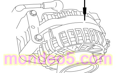 Generator case
|
-
For all other engines, measure
|
Positive Lead
|
Measurement / Action
|
Negative Lead
|
|
C102C-1
|
|
Generator case
|
Is the resistance greater than 25K ohms?
|
| I9
CHECK THE RESISTANCE OF THE VOLTAGE REGULATOR INTERNAL CIRCUITS TO GROUND
|
-
For the 2.0L EcoBoost, measure:
|
Positive Lead
|
Measurement / Action
|
Negative Lead
|
|
C1558A-1
|
|
Ground
|
|
C1558A-2
|
|
Ground
|
|
C1558A-3
|
|
Ground
|
-
For all other engines, measure:
|
Positive Lead
|
Measurement / Action
|
Negative Lead
|
|
C102A-1
|
|
Ground
|
|
C102A-2
|
|
Ground
|
|
C102A-3
|
|
Ground
|
Are the resistances greater than 10,000 ohms?
|
| I10
COMPARE THE GENMON AND THE GENCMD PIDS
|
-
Connect
C1915B (1.5L EcoBoost).
-
Connect
C1232B (1.6L EcoBoost).
-
Connect
C1381B (2.0L EcoBoost).
-
Connect
C1551B (2.5L Duratec).
-
For the 2.0L EcoBoost, connect:
|
Positive Lead
|
Measurement / Action
|
Negative Lead
|
|
C1558A-1
|
|
C1558A-2
|
-
For all other engines, connect:
|
Positive Lead
|
Measurement / Action
|
Negative Lead
|
|
C102A-1
|
|
C102A-2
|
-
Using a diagnostic scan tool, view
Parameter Identifications (PIDs).
-
Using the active command, set the
GENVDSD to 14 volts.
-
Monitor the
Parameter Identifications (PIDs) GENMON and GENCMD.
-
Perform a wiggle test of the generator wiring and connections.
Do the Parameter Identifications (PIDs) read within 5% of each other?
| No
|
REMOVE the fused jumper wire. GO to
I11
|
|
| I11
CHECK FOR CORRECT PCM (POWERTRAIN CONTROL MODULE)
OPERATION
|
-
Disconnect and inspect all
connectors.
-
Repair:
-
corrosion (install new connector or terminals – clean module pins)
-
damaged or bent pins – install new terminals/pins
-
pushed-out pins – install new pins as necessary
-
Reconnect the
connectors. Make sure they seat and latch correctly.
-
Operate the system and determine if the concern is still present.
Is the concern still present?
| Yes
|
CHECK
for any applicable Technical Service Bulletins (TSBs). If a
exists for this concern, DISCONTINUE this test and FOLLOW the
instructions. If no Technical Service Bulletins (TSBs) address this concern, INSTALL a new
. For 1.5L EcoBoost,
REFER to:
Powertrain Control Module (PCM)
(303-14A Electronic Engine Controls - 1.5L EcoBoost (118kW/160PS), Removal and Installation).
For 1.6L EcoBoost, REFER to:
Powertrain Control Module (PCM)
(303-14B Electronic Engine Controls - 1.6L EcoBoost (132kW/180PS) - Sigma, Removal and Installation).
For 2.0L EcoBoost, REFER to:
Powertrain Control Module (PCM)
(303-14C Electronic Engine Controls - 2.0L EcoBoost (184kW/250PS) - MI4, Removal and Installation).
For 2.5L Duratec REFER to:
Powertrain Control Module (PCM)
(303-14D Electronic Engine Controls - 2.5L Duratec (125kW/170PS), Removal and Installation).
CLEAR all Diagnostic Trouble Codes (DTCs) in all modules.
|
| No
|
The system is operating correctly at this time. The concern may have been caused by module connections. ADDRESS the root cause
of any connector or pin issues.
|
|
Component Test - Generator Clutch
-
Remove the generator. For 1.5L EcoBoost,
REFER to:
Generator - 1.5L EcoBoost (118kW/160PS)
(414-02 Generator and Regulator, Removal and Installation).
For 1.6L EcoBoost, REFER to:
Generator - 1.6L EcoBoost (132kW/180PS) - Sigma
(414-02 Generator and Regulator, Removal and Installation).
For 2.0L EcoBoost, REFER to:
Generator - 2.0L EcoBoost (184kW/250PS) - MI4
(414-02 Generator and Regulator, Removal and Installation).
For 2.5L Duratec, REFER to:
Generator - 2.5L Duratec (125kW/170PS)
(414-02 Generator and Regulator, Removal and Installation).
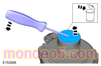
-
Using a small screwdriver or similar tool, insert the tool through the rubber button on the center of the pulley cap and pry
off the cap. Discard the cap. A new cap must be installed if the clutch is OK.
-
Using a 17 mm hex tool bit (such as a Snap-on® SAM17E2 or equivalent) and socket wrench, insert the 17 mm hex tool bit into
the end of the clutch shaft.
-
While holding the clutch pulley firmly by hand, turn the clutch shaft clockwise. The shaft should rotate smooth and freely.
If the shaft rotation is rough or seized, install a new generator clutch.
REFER to:
Generator Pulley - 1.5L EcoBoost (118kW/160PS)/1.6L EcoBoost (132kW/180PS) - Sigma/2.0L EcoBoost (184kW/250PS) - MI4/2.5L
Duratec (125kW/170PS)
(414-02 Generator and Regulator, Removal and Installation).
-
While holding the clutch pulley firmly by hand, turn the clutch shaft counterclockwise. There should be some resistance (a
spring feel). If the shaft rotates freely, install a new generator clutch.
REFER to:
Generator Pulley - 1.5L EcoBoost (118kW/160PS)/1.6L EcoBoost (132kW/180PS) - Sigma/2.0L EcoBoost (184kW/250PS) - MI4/2.5L
Duratec (125kW/170PS)
(414-02 Generator and Regulator, Removal and Installation).
Copyright © Ford Motor Company
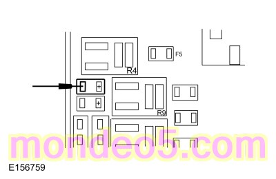 BJB
fuse 7
BJB
fuse 7