| 419-03A Cruise Control
|
2013 - 2014 Fusion
|
| Diagnosis and Testing
|
Procedure revision date:
07/9/2013
|
Cruise Control
DTC Charts
Diagnostics in this manual assume a certain skill level and knowledge of Ford-specific diagnostic practices.
REFER to:
Diagnostic Methods
(100-00 General Information, Description and Operation).
DTC Chart: Powertrain Control Module (PCM)
Chart
DTC Chart: Steering Column Control Module (SCCM)
Chart
DTC Chart: Cruise Control Module (CCM)
Chart
|
DTC
|
Description
|
Action
|
|
B142E:78
|
Forward Looking Sensor Horizontal Alignment: Alignment or Adjustment Incorrect
|
GO to Pinpoint Test I
|
|
B1432:78
|
Forward Looking Sensor Vertical Alignment: Alignment of Adjustment Incorrect
|
This
can only be set at the assembly plant during the plant alignment process. If
B1432:78 sets, a reflash of the
and the vertical and horizontal aim procedure must be performed.
REFER to:
Cruise Control Radar Alignment
(419-03A Cruise Control, General Procedures).
|
|
B1433:54
|
Forward Looking Sensor Alignment: Missing Calibration
|
GO to Pinpoint Test I
|
|
C0072:00
|
Brake Temperature Too High: No Sub Type Information
|
REFER to:
Anti-Lock Brake System (ABS) and Stability Control - Vehicles Built Up To: 03-June-2013
(206-09 Anti-Lock Brake System (ABS) and Stability Control, Diagnosis and Testing).
|
|
C1132:4B
|
Head Up Display: Over Temperature
|
REFER to:
Collision Warning System
(419-03B Collision Warning System, Diagnosis and Testing).
|
|
C1A67:96
|
Forward Looking Sensor: Component Internal Failure
|
GO to Pinpoint Test J
|
|
C1A67:97
|
Forward Looking Sensor: Component or System Operation Obstructed or Blocked
|
GO to Pinpoint Test K
|
|
C1A67:98
|
Forward Looking Sensor: Component or System Over Temperature
|
The
was over-temperature. This may occur during extended use of extremely high weather temperatures. The adaptive cruise control
system operation resumes after the
cools.
|
|
U0001:88
|
High Speed CAN Communication Bus: Bus Off
|
REFER to:
Communications Network
(418-00 Module Communications Network, Diagnosis and Testing).
|
|
U0100:00
|
Lost Communication With ECM/PCM "A": No Sub Type Information
|
GO to Pinpoint Test L
|
|
U0101:00
|
Lost Communication with TCM: No Sub Type Information
|
GO to Pinpoint Test L
|
|
U0121:00
|
Lost Communication With Anti-Lock Brake System (ABS) Control Module: No Sub Type Information
|
GO to Pinpoint Test G
|
|
U0140:00
|
Lost Communication With Body Control Module: No Sub Type Information
|
GO to Pinpoint Test M
|
|
U0151:00
|
Lost Communication With Restraints Control Module: No Sub Type Information
|
GO to Pinpoint Test N
|
|
U0155:00
|
Lost Communication With Instrument Panel Cluster (IPC) Control Module: No Sub Type Information
|
GO to Pinpoint Test O
|
|
U0158:00
|
Lost Communication With Head Up Display: No Sub Type Information
|
GO to Pinpoint Test P
|
|
U0212:00
|
Lost Communication With Steering Column Control Module: No Sub Type Information
|
GO to Pinpoint Test Q
|
|
U0401:86
|
Invalid Data Received From ECM/PCM "A": Signal Invalid
|
This
sets when the
receives invalid network data from the
with a faulted vehicle speed sensor signal, accelerator pedal position signal or cruise control switch input. RETRIEVE and
REPAIR all non-network Diagnostic Trouble Codes (DTCs) in the other modules on the network.
|
|
U0402:86
|
Invalid Data Received From TCM: Signal Invalid
|
This
sets when the
receives invalid network data from the
with a faulted gear lever position input. RETRIEVE and REPAIR all non-network Diagnostic Trouble Codes (DTCs) in other modules
on the network.
|
|
U0418:86
|
Invalid Data Received From Brake System Control Module: Signal Invalid
|
This
sets when the
receives invalid network data from the
module with a faulted brake signal input, yaw rate input, steering wheel angle input or vehicle speed input. RETRIEVE and
REPAIR all non-network Diagnostic Trouble Codes (DTCs) in the other modules on the network.
|
|
U0423:82
|
Invalid Data Received From Instrument Panel Cluster Control Module: Alive/Sequence Counter Incorrect/ Not Updated
|
GO to Pinpoint Test V
|
|
U0429:86
|
Invalid Data Received From Steering Column Control Module: Signal Invalid
|
This
sets when the
receives invalid network data from the
with a faulted cruise control switch input. RETRIEVE and REPAIR all non-network Diagnostic Trouble Codes (DTCs) in the other
modules on the network.
|
|
U0452:86
|
Invalid Data Received From Restraints Control Module: Signal Invalid
|
This
sets when the
receives invalid network data from the
with a faulted yaw rate input. RETRIEVE and REPAIR all non-network Diagnostic Trouble Codes (DTCs) in the other modules on
the network. CHECK the vehicle service history for recent service actions related to this module. This
sets due to incomplete or incorrect
procedures. If there have been recent service actions with this module, REPEAT the
procedure as directed by the diagnostic scan tool.
REFER to:
Module Configuration - System Operation and Component Description
(418-01 Module Configuration, Description and Operation).
If there have been no recent service actions, INSTALL a new module to correct the failure to retain configuration data. REFER to:
Cruise Control Module (CCM)
(419-03A Cruise Control, Removal and Installation).
|
|
U0459:86
|
Invalid Data Received From Head Up Display: Signal Invalid
|
GO to Pinpoint Test R
|
|
U2100:00
|
Initial Configuration Not Complete: No Sub Type Information
|
This
sets when the
configuration has not been completed. CARRY OUT the
(when the original module is not available) for the module in question as directed by the diagnostic scan tool.
REFER to:
Module Configuration - System Operation and Component Description
(418-01 Module Configuration, Description and Operation).
|
|
U2300:55
|
Central Configuration: Not Configured
|
This
sets when the
detects that the
is not configured correctly. CARRY OUT the
(when the original module is not available) for the module in question as directed by the diagnostic scan tool.
REFER to:
Module Configuration - System Operation and Component Description
(418-01 Module Configuration, Description and Operation).
|
|
U2300:64
|
Central Configuration: Signal Plausibility Failure
|
This
sets when the
detects that the
is not configured correctly. CARRY OUT the
(when the original module is not available) for the module in question as directed by the diagnostic scan tool.
REFER to:
Module Configuration - System Operation and Component Description
(418-01 Module Configuration, Description and Operation).
|
|
U3000:41
|
Control Module: General Checksum Failure
|
CLEAR the Diagnostic Trouble Codes (DTCs). RETEST the adaptive cruise control system. REPEAT the self test. If
U3000:41 is retrieved again, INSTALL a new
.
REFER to:
Cruise Control Module (CCM)
(419-03A Cruise Control, Removal and Installation).
|
|
U3000:42
|
Control Module: General Memory Failure
|
CLEAR the Diagnostic Trouble Codes (DTCs). RETEST the adaptive cruise control system. REPEAT the self-test. If
U3000:42 is retrieved again, INSTALL a new
.
REFER to:
Cruise Control Module (CCM)
(419-03A Cruise Control, Removal and Installation).
|
|
U3000:44
|
Control Module: Data Memory Failure
|
CLEAR the Diagnostic Trouble Codes (DTCs). RETEST the adaptive cruise control system. REPEAT the self-test. If
U3000:44 is retrieved again, INSTALL a new
.
REFER to:
Cruise Control Module (CCM)
(419-03A Cruise Control, Removal and Installation).
|
|
U3000:49
|
Control Module: Internal Electronic Failure
|
If
U3000:49 is retrieved again, INSTALL a new
.
REFER to:
Cruise Control Module (CCM)
(419-03A Cruise Control, Removal and Installation).
|
|
U3000:63
|
Control Module: Circuit/Component Protection Time-Out
|
GO to Pinpoint Test S
|
|
U3002:62
|
Vehicle Identification Number: Signal Compare Failure
|
This
sets when the stored
in the
does not match the
defined in the
. This may indicate that the original
is not installed in the vehicle, and has not been configured correctly. CARRY OUT the
(when the original module is not available) for the module in question as directed by the diagnostic scan tool.
REFER to:
Module Configuration - System Operation and Component Description
(418-01 Module Configuration, Description and Operation).
|
|
U3003:16
|
Battery Voltage: Circuit Voltage Below Threshold
|
GO to Pinpoint Test T
|
|
U3003:17
|
Battery Voltage: Circuit Voltage Above Threshold
|
GO to Pinpoint Test U
|
DTC Chart: Anti-Lock Brake System (ABS) Module
Module
Chart
|
DTC
|
Description
|
Action
|
|
U0405:86
|
Invalid Data Received From Cruise Control Module: Signal Invalid
|
This
sets when the
module receives invalid network data from the
. RETRIEVE and REPAIR all non-network Diagnostic Trouble Codes (DTCs) in the
and other modules on the network.
|
|
U2107:00
|
Collision Mitigation By Braking: No Sub Type Information
|
This
sets in the
module due to long and too often collision mitigation brake requests from the
. RETRIEVE and REPAIR all non-network Diagnostic Trouble Codes (DTCs) in the
and other modules on the network.
|
|
U2107:68
|
Collision Mitigation By Braking: Event Information
|
This
is set in the
module due to a high acceleration value detected that differs from request, which can be caused by an abrupt vehicle stop
or module failure. RETRIEVE and REPAIR all Diagnostic Trouble Codes (DTCs) in the
and
module.
|
|
U2108:00
|
Adaptive Cruise Control: No Sub Type Information
|
This
is set in the
module when the adaptive cruise control does not deactivate when the brake pedal is pressed. To diagnose inoperative adaptive
cruise control,
GO to Pinpoint Test B
|
|
U2108:68
|
Adaptive Cruise Control: Event Information
|
This
is set in the
module when the module detects over-braking during automated vehicle deceleration. If the vehicle deceleration exceeds the
3.2 m/s threshold, the
is stored and the adaptive cruise control is deactivated until the next ignition cycle. RETRIEVE and REPAIR all Diagnostic
Trouble Codes (DTCs) in the
and
module.
|
|
All other Diagnostic Trouble Codes (DTCs)
|
–
|
REFER to:
Anti-Lock Brake System (ABS) and Stability Control - Vehicles Built Up To: 03-June-2013
(206-09 Anti-Lock Brake System (ABS) and Stability Control, Diagnosis and Testing).
|
Symptom Chart(s)
Symptom Chart: Cruise Control
Diagnostics in this manual assume a certain skill level and knowledge of Ford-specific diagnostic practices.
REFER to:
Diagnostic Methods
(100-00 General Information, Description and Operation).
Symptom Chart - Non-Adaptive Cruise Control
|
Condition
|
Possible Sources
|
Actions
|
|
The cruise control is inoperative
|
Refer to the Pinpoint Test
|
GO to Pinpoint Test A
|
|
The cruise control indicator lamp is never/always on
|
-
Wiring, terminals and connectors
-
-
|
REFER to:
Instrumentation, Message Center and Warning Chimes
(413-01 Instrumentation, Message Center and Warning Chimes, Diagnosis and Testing).
|
|
The cruise control switch is inoperative/does not operate correctly
|
Refer to the Pinpoint Test
|
GO to Pinpoint Test A
|
|
The cruise control does not disengage when the clutch pedal is applied
|
Refer to the Pinpoint Test
|
GO to Pinpoint Test C
|
|
The cruise control cannot set above 105 kmh (65 mph), 113 km/h (70 mph), 121 km/h (75 mph), or 129 km/h (80 mph)
|
A MyKey® restricted key is in use and MyKey® max speed limiter is turned on
|
VERIFY whether a MyKey® restricted key is in use.
REFER to:
Key Programming Using Two Programmed Keys
(419-01B Passive Anti-Theft System (PATS), General Procedures).
With an admin key, VERIFY if MyKey® max speed limiter is turned on. REFER to the Owner's Literature. If necessary, VERIFY
cruise control normal operation with an admin key.
|
Symptom Chart - Adaptive Cruise Control
|
Condition
|
Possible Sources
|
Actions
|
|
The adaptive cruise control is inoperative
|
Refer to the Pinpoint Test
|
GO to Pinpoint Test B
|
|
The cruise control indicator lamp is never/always on
|
-
Wiring, terminals and connectors
-
-
|
REFER to:
Instrumentation, Message Center and Warning Chimes
(413-01 Instrumentation, Message Center and Warning Chimes, Diagnosis and Testing).
|
|
The cruise control switch is inoperative/does not operate correctly
|
Refer to the Pinpoint Test
|
GO to Pinpoint Test B
|
|
The adaptive cruise control does not function in rain or snow conditions
|
Refer to the Pinpoint Test
|
GO to Pinpoint Test K
|
|
"ADAPTIVE CRUISE NOT AVAILABLE SENSOR BLOCKED SEE MANUAL" message in the
message center
|
Refer to the Pinpoint Test
|
GO to Pinpoint Test K
|
|
The adaptive cruise control indicator lamp is never/ always on
|
-
Wiring, terminals and connectors
-
-
|
REFER to:
Instrumentation, Message Center and Warning Chimes
(413-01 Instrumentation, Message Center and Warning Chimes, Diagnosis and Testing).
|
|
Unexpected adaptive cruise control braking
|
|
The adaptive cruise control system can occasionally detect and respond to out-of path vehicles, especially on curves, entry/exit
ramps or when changing lanes. CHECK the
and front bumper cover for damage. RETEST the adaptive cruise control system.
|
|
Lack of adaptive cruise control braking
|
|
The adaptive cruise control system may not detect and respond to vehicles carrying out close cut-ins or on tight curves (especially
for vehicles on the passenger side) due to limited
field of view. CHECK the
and front bumper cover for damage. If no damage is observed, RETEST the adaptive cruise control system.
|
|
Noise during adaptive cruise control braking
|
|
The driver can detect some noise at low speeds when adaptive cruise control braking occurs. If braking noise continues,
REFER to:
Brake System
(206-00 Brake System - General Information, Diagnosis and Testing).
|
|
The cruise control cannot set above 105 km/h (65 mph), 113 km/h (70 mph), 121 km/h (75 mph), or 129 km/h (80 mph)
|
A MyKey® restricted key is in use and MyKey® max speed limiter is turned on
|
VERIFY whether a MyKey® restricted key is in use.
REFER to:
Key Programming Using Two Programmed Keys
(419-01B Passive Anti-Theft System (PATS), General Procedures).
With an admin key, VERIFY if MyKey® max speed limiter is turned on. REFER to the Owner's Literature. If necessary, VERIFY
cruise control normal operation with an admin key.
|
Pinpoint Tests
The Cruise Control Is Inoperative
Refer to Wiring Diagrams Cell 31 for schematic and connector information.
Normal Operation and Fault Conditions
REFER to:
Steering Wheel and Column Electrical Components - System Operation and Component Description
(211-05 Steering Wheel and Column Electrical Components, Description and Operation).
REFER to:
Cruise Control - System Operation and Component Description
(419-03A Cruise Control, Description and Operation).
DTC Fault Trigger Conditions
|
DTC
|
Description
|
Action
|
|
B137F:09
|
Steering Wheel Left Switch Pack: Component Failure
|
A continuous and on-demand
that sets when one or more of the cruise control switches are stuck.
|
|
B137F:11
|
Steering Wheel Left Switch Pack: Circuit Short to Ground
|
A continuous and on-demand
that sets when the cruise control switch circuits are shorted to ground.
|
|
B137F:17
|
Steering Wheel Left Switch Pack: Circuit Voltage Above Threshold
|
A continuous and on-demand
that sets when the cruise control switch circuits are shorted to voltage.
|
Possible Sources
-
Wiring, terminals or connectors
-
-
Cruise control switch
-
Digital
sensor (if equipped)
-
-
switch
-
sensor (if equipped)
PINPOINT TEST A : THE CRUISE CONTROL IS INOPERATIVE
| A1
CHECK FOR DIAGNOSTIC TROUBLE CODES (DTCS)
|
-
Using a diagnostic scan tool, perform the
self-test.
-
Using a diagnostic scan tool, perform the
self-test.
Are any Diagnostic Trouble Codes (DTCs) recorded?
| Yes
|
REFER to the
Chart or the
in this section.
|
|
| A2
CHECK THE STOPLAMP SWITCH (BOO1) AND CRUISE CONTROL DEACTIVATOR SWITCH (BOO2) PARAMETER IDENTIFICATIONS (PIDS)
|
-
Using a diagnostic scan tool, view
Parameter Identifications (PIDs).
-
Using the table, monitor the BOO1 (stoplamp switch) and BOO2 (cruise control deactivator switch) Parameter Identifications
(PIDs) while applying and releasing the brake pedal.
|
Brake Pedal Position
|
BOO1 PID
|
BOO2 PID
|
|
Released
|
Off
|
Off
|
|
Applied
|
On
|
On
|
Do the
values agree with the brake pedal position?
| Yes
|
For manual transmission, GO to
A3
For automatic transmission, GO to
A5
|
|
| A3
CHECK THE CPP (CLUTCH PEDAL POSITION)
SENSOR (CPP_TOP) PID (PARAMETER IDENTIFICATION)
|
-
Using a diagnostic scan tool, view
Parameter Identifications (PIDs).
-
Using the table, monitor the
CPP_TOP
while pressing and releasing the clutch pedal.
|
Cluch Pedal Position
|
CPP_TOP PID
|
|
Released
|
No
|
|
Pressed
|
Yes
|
Does the
value agree with the clutch pedal position?
| No
|
If the Parameter Identification (PID) value always reads YES (pressed), GO to
A4
If the Parameter Identification (PID) value always reads NO (released),
GO to Pinpoint Test C
|
|
| A4
CHECK THE CLUTCH PEDAL (CPP_TOP) PID (PARAMETER IDENTIFICATION)
WITH THE CPP (CLUTCH PEDAL POSITION)
SENSOR DISCONNECTED
|
-
Using a diagnostic scan tool, view
Parameter Identifications (PIDs).
-
Monitor the clutch pedal CPP_TOP
.
Does the
read NO?
| Yes
|
INSTALL a new
sensor.
|
|
| A5
CHECK THE CRUISE CONTROL SWITCH (SCCS) PID (PARAMETER IDENTIFICATION)
|
-
Using a diagnostic scan tool, view
Parameter Identifications (PIDs).
-
Using the table, press each cruise control switch while monitoring the cruise control switch (SCCS)
.
|
Cruise Control Switch
|
SCCS PID Value
|
|
-
|
None pressed
|
|
RES
|
Resume
|
|
CNCL
|
Cancel
|
|
ON/OFF (pressed up)
|
On
|
|
ON/OFF (pressed down)
|
Off
|
|
SET (pressed up)
|
SET/+
|
|
SET (pressed down)
|
SET/-
|
Does the
value agree with the switch position?
| Yes
|
If equipped with manual transmission, GO to
A11
If equipped with automatic transmission, GO to
A6
|
| No
|
If only one switch does not display the correct
value, INSTALL a new LH steering wheel switch.
REFER to:
Steering Wheel Multifunction Switch
(211-05 Steering Wheel and Column Electrical Components, Removal and Installation).
If multiple switches do not display the correct
value, GO to
A7
|
|
| A6
MONITOR THE PCM (POWERTRAIN CONTROL MODULE)
PID TR PARAMETER IDENTIFICATION (PID)
|
-
Using a diagnostic scan tool, view
Parameter Identifications (PIDs).
-
Monitor the
PID TR Parameter Identification (PID).
Does the
value agree with the
selector lever position?
| No
|
Refer to the appropriate section in Group 307 for the procedure.
|
|
| A7
CHECK FOR VOLTAGE TO THE CRUISE CONTROL SWITCHES
|
-
Remove the driver airbag.
REFER to:
Driver Airbag
(501-20B Supplemental Restraint System, Removal and Installation).
-
Disconnect LH Steering Wheel Switch C2490.
-
Measure:
|
Positive Lead
|
Measurement / Action
|
Negative Lead
|
|
C2490-4
|

|
C2490-5
|
|
C2490-6
|
|
C2490-5
|
|
C2490-7
|
|
C2490-5
|
Is the voltage approximately 5 volts?
| Yes
|
TURN ignition off and WAIT one minute. INSTALL a new LH steering wheel switch.
REFER to:
Steering Wheel Multifunction Switch
(211-05 Steering Wheel and Column Electrical Components, Removal and Installation).
INSTALL the driver airbag.
REFER to:
Driver Airbag
(501-20B Supplemental Restraint System, Removal and Installation).
|
|
| A8
CHECK THE STEERING WHEEL SWITCH HARNESS FOR AN OPEN
|
-
Disconnect Clockspring C218B.
-
Measure:
|
Positive Lead
|
Measurement / Action
|
Negative Lead
|
|
C2490-4
|

|
C218B-7
|
|
C2490-5
|
|
C218B-8
|
|
C2490-6
|
|
C218B-15
|
|
C2490-7
|
|
C218B-6
|
Are the resistances less than 3 ohms?
| No
|
INSTALL a new steering wheel.
REFER to:
Steering Wheel
(211-04 Steering Column, Removal and Installation).
|
|
| A9
CHECK THE STEERING WHEEL SWITCH CIRCUITS THROUGH THE CLOCKSPRING FOR AN OPEN
|
-
Disconnect Clockspring C218C.
Are the resistances less than 3 ohms?
| No
|
INSTALL a new clockspring.
REFER to:
Clockspring
(501-20B Supplemental Restraint System, Removal and Installation).
|
|
| A10
CHECK FOR CORRECT SCCM (STEERING COLUMN CONTROL MODULE)
OPERATION
|
-
Disconnect and inspect all
connectors.
-
Repair:
-
corrosion (install new connector or terminals - clean module pins)
-
damaged or bent pins - install new terminals/pins
-
pushed-out pins - install new pins as necessary
-
Reconnect the
connectors. Make sure they seat and latch correctly.
-
Operate the system and determine if the concern is still present.
Is the concern still present?
| Yes
|
CHECK
for any applicable Technical Service Bulletins (TSBs). If a
exists for this concern, DISCONTINUE this test and FOLLOW
instructions. If no Technical Service Bulletins (TSBs) address this concern, INSTALL a new
.
REFER to:
Steering Column Control Module (SCCM)
(211-05 Steering Wheel and Column Electrical Components, Removal and Installation).
|
| No
|
The system is operating correctly at this time. The concern may have been caused by module connections. ADDRESS the root cause
of any connector or pin issues.
|
|
| A11
CHECK FOR CORRECT PCM (POWERTRAIN CONTROL MODULE)
OPERATION
|
-
Disconnect and inspect all
connectors.
-
Repair:
-
corrosion (install new connector or terminals - clean module pins)
-
damaged or bent pins - install new terminals/pins
-
pushed-out pins - install new pins as necessary
-
Reconnect the
connectors. Make sure they seat and latch correctly.
-
Operate the system and determine if the concern is still present.
Is the concern still present?
| Yes
|
CHECK
for any applicable TSBs. If a
exists for this concern, DISCONTINUE this test and FOLLOW
instructions. If no TSBs address this concern, INSTALL a new
.
Refer to the appropriate section in Group 303 for the procedure.
|
| No
|
The system is operating correctly at this time. The concern may have been caused by module connections. ADDRESS the root cause
of any connector or pin issues.
|
|
The Adaptive Cruise Control Is Inoperative
Refer to Wiring Diagrams Cell 31 for schematic and connector information.
Normal Operation and Fault Conditions
REFER to:
Steering Wheel and Column Electrical Components - System Operation and Component Description
(211-05 Steering Wheel and Column Electrical Components, Description and Operation).
REFER to:
Cruise Control - System Operation and Component Description
(419-03A Cruise Control, Description and Operation).
Fault Trigger Conditions
|
DTC
|
Description
|
Action
|
|
B137F:09
|
Steering Wheel Left Switch Pack: Component Failure
|
A continuous and on-demand
that sets when one or more of the cruise control switches are stuck.
|
|
B137F:11
|
Steering Wheel Left Switch Pack: Circuit Short to Ground
|
A continuous and on-demand
that sets when the cruise control switch circuits are shorted to ground.
|
|
B137F:17
|
Steering Wheel Left Switch Pack: Circuit Voltage Above Threshold
|
A continuous and on-demand
that sets when the cruise control switch circuits are shorted to voltage.
|
|
U2108:00
|
Adaptive Cruise Control: No Sub Type Information
|
This
is set in the
module when the adaptive cruise control does not deactivate when the brake pedal is pressed.
|
Possible Sources
-
Wiring, terminals or connectors
-
Cruise control switch
-
Cruise control deactivator switch
-
Digital
sensor
-
Stoplamp switch
-
Vehicle speed signal
-
-
module
-
-
-
PINPOINT TEST B : THE ADAPTIVE CRUISE CONTROL IS INOPERATIVE
| B1
CHECK FOR DIAGNOSTIC TROUBLE CODES (DTCS)
|
-
Using a diagnostic scan tool, perform the
self-test.
-
Using a diagnostic scan tool, perform the
self-test.
-
Using a diagnostic scan tool, perform the self-test.
-
Using a diagnostic scan tool, perform the
module self-test.
Are any Diagnostic Trouble Codes (DTCs) recorded?
| Yes
|
For
,
,
, and
module Diagnostic Trouble Codes (DTCs), REFER to the
Charts in this section.
|
|
| B2
CHECK FOR LOST COMMUNICATION DIAGNOSTIC TROUBLE CODES (DTCS)
|
-
Clear continuous Diagnostic Trouble Codes (DTCs) from all modules.
-
Wait at least 10 seconds. Retrieve continuous Diagnostic Trouble Codes (DTCs) from all modules.
Are any lost communication Diagnostic Trouble Codes (DTCs) set in the
?
| Yes
|
REFER to the
Chart in this section.
|
|
| B3
CHECK THE STOPLAMP SWITCH (BOO1) AND CRUISE CONTROL DEACTIVATOR SWITCH (BOO2) PARAMETER IDENTIFICATIONS (PIDS)
|
-
Using a diagnostic scan tool, view
Parameter Identifications (PIDs).
-
Using the table, monitor the BOO1 (stoplamp switch) and BOO2 (cruise control deactivator switch) Parameter Identifications
(PIDs) while applying and releasing the brake pedal.
|
Brake Pedal Position
|
BOO1 PID
|
BOO2 PID
|
|
Released
|
On
|
On
|
|
Applied lightly
|
On
|
Off
|
|
Applied firmly
|
Off
|
Off
|
Do the Parameter Identification (PID) values agree with the brake pedal position?
|
| B4
CHECK THE CRUISE CONTROL SWITCH (SCCS) PARAMETER IDENTIFICATION (PID)
|
-
Using a diagnostic scan tool, view
Parameter Identifications (PIDs).
-
Using the table, press each cruise control switch while monitoring the cruise control switch (SCCS) Parameter Identification
(PID).
|
Cruise Control Switch
|
SCCS PID Value
|
|
-
|
None pressed
|
|
RES
|
Resume
|
|
CNCL
|
Cancel
|
|
ON/OFF (pressed up)
|
On
|
|
ON/OFF (pressed down)
|
Off
|
|
SET (pressed up)
|
SET/+
|
|
SET (pressed down)
|
SET/-
|
Does the Parameter Identification (PID) value agree with the switch position?
| No
|
If only one switch does not display the correct Parameter Identification (PID) value, INSTALL a new LH steering wheel switch.
REFER to:
Steering Wheel Multifunction Switch
(211-05 Steering Wheel and Column Electrical Components, Removal and Installation).
If multiple switches do not display the correct Parameter Identification (PID) value, GO to
B6
|
|
| B5
MONITOR THE PCM (POWERTRAIN CONTROL MODULE)
PID TR PARAMETER IDENTIFICATION (PID)
|
-
Using a diagnostic scan tool, view
Parameter Identifications (PIDs).
-
Monitor the
PID TR Parameter Identification (PID).
Does the Parameter Identification (PID) value agree with the
selector lever position?
| No
|
Refer to the appropriate section in Group 307 for the procedure.
|
|
| B6
CHECK FOR VOLTAGE TO THE CRUISE CONTROL SWITCHES
|
-
Remove the driver airbag.
REFER to:
Driver Airbag
(501-20B Supplemental Restraint System, Removal and Installation).
-
Disconnect LH Steering Wheel Switch C2490.
-
Measure:
|
Positive Lead
|
Measurement / Action
|
Negative Lead
|
|
C2490-4
|
|
C2490-5
|
|
C2490-6
|
|
C2490-5
|
|
C2490-7
|
|
C2490-5
|
Is the voltage approximately 5 volts?
| Yes
|
TURN ignition off and WAIT one minute. INSTALL a new LH steering wheel switch.
REFER to:
Steering Wheel Multifunction Switch
(211-05 Steering Wheel and Column Electrical Components, Removal and Installation).
INSTALL the driver airbag.
REFER to:
Driver Airbag
(501-20B Supplemental Restraint System, Removal and Installation).
|
|
| B7
CHECK THE STEERING WHEEL SWITCH HARNESS FOR AN OPEN
|
-
Disconnect Clockspring C218B.
-
Measure:
|
Positive Lead
|
Measurement / Action
|
Negative Lead
|
|
C2490-4
|
|
C218B-7
|
|
C2490-5
|
|
C218B-8
|
|
C2490-6
|
|
C218B-15
|
|
C2490-7
|
|
C218B-6
|
Are the resistances less than 3 ohms?
| No
|
INSTALL a new steering wheel.
REFER to:
Steering Wheel
(211-04 Steering Column, Removal and Installation).
|
|
| B8
CHECK THE STEERING WHEEL SWITCH CIRCUITS THROUGH THE CLOCKSPRING FOR AN OPEN
|
-
Disconnect Clockspring C218C.
Are the resistances less than 3 ohms?
| No
|
INSTALL a new clockspring.
REFER to:
Clockspring
(501-20B Supplemental Restraint System, Removal and Installation).
|
|
| B9
CHECK FOR CORRECT SCCM (STEERING COLUMN CONTROL MODULE)
OPERATION
|
-
Disconnect and inspect all
connectors.
-
Repair:
-
corrosion (install new connector or terminals - clean module pins)
-
damaged or bent pins - install new terminals/pins
-
pushed-out pins - install new pins as necessary
-
Reconnect the
connectors. Make sure they seat and latch correctly.
-
Operate the system and determine if the concern is still present.
Is the concern still present?
| Yes
|
CHECK
for any applicable TSBs. If a
exists for this concern, DISCONTINUE this test and FOLLOW
instructions. If no TSBs address this concern, INSTALL a new
.
REFER to:
Steering Column Control Module (SCCM)
(211-05 Steering Wheel and Column Electrical Components, Removal and Installation).
|
| No
|
The system is operating correctly at this time. The concern may have been caused by module connections. ADDRESS the root cause
of any connector or pin issues.
|
|
| B10
CHECK FOR CORRECT PCM (POWERTRAIN CONTROL MODULE)
OPERATION
|
-
Disconnect and inspect all
connectors.
-
Repair:
-
corrosion (install new connector or terminals - clean module pins)
-
damaged or bent pins - install new terminals/pins
-
pushed-out pins - install new pins as necessary
-
Reconnect the
connectors. Make sure they seat and latch correctly.
-
Operate the system and determine if the concern is still present.
Is the concern still present?
| Yes
|
CHECK
for any applicable TSBs. If a
exists for this concern, DISCONTINUE this test and FOLLOW
instructions. If no TSBs address this concern, INSTALL a new
.
Refer to the appropriate section in Group 303 for the procedure.
|
| No
|
The system is operating correctly at this time. The concern may have been caused by module connections. ADDRESS the root cause
of any connector or pin issues.
|
|
The Cruise Control Does Not Disengage When The Clutch Pedal Is Applied
Refer to Wiring Diagrams Cell 31 for schematic and connector information.
Normal Operation and Fault Conditions
REFER to:
Cruise Control - System Operation and Component Description
(419-03A Cruise Control, Description and Operation).
Fault Trigger Conditions
|
DTC
|
Description
|
Action
|
|
P08A9
|
Clutch Pedal Sensor 1, Out of Limits LOW
|
This
sets when the
detects an open on the
sensor circuit. The
sensor monitors the position of the clutch pedal during normal driving cycles. Any fault detected by the
related to
sensor reliability will disable the cruise control system, and the
will set in continuous memory.
|
|
P08AA
|
Clutch Pedal Sensor 1, Out of Limits HIGH
|
This
sets when the
detects a short to voltage on the
sensor circuit.The
sensor monitors the position of the clutch pedal during normal driving cycles. Any fault detected by the
related to
sensor reliability will disable the cruise control system, and the
will set in continuous memory.
|
|
P08B6
|
Clutch Pedal Sensor 2, Out of Limits LOW
|
This
sets when the
detects an open on the
sensor circuit. The
sensor monitors the position of the clutch pedal during normal driving cycles. Any fault detected by the
related to
sensor reliability will disable the cruise control system, and the
will set in continuous memory.
|
|
P08B7
|
Clutch Pedal Sensor 2, Out of Limits HIGH
|
This
sets when the
detects a short to voltage on the
sensor circuit.The
sensor monitors the position of the clutch pedal during normal driving cycles. Any fault detected by the
related to
sensor reliability will disable the cruise control system, and the
will set in continuous memory.
|
|
P08B9
|
Clutch Pedal Sensor 1 and 2 Do Not Match Expected Values
|
This
sets when the
does not sense the correct sequence of the
sensor input signals when the clutch pedal is pressed and released.
|
Possible Sources
-
Wiring, terminals or connectors
-
sensor
-
PINPOINT TEST C : THE CRUISE CONTROL DOES NOT DISENGAGE WHEN THE CLUTCH PEDAL IS APPLIED
| C1
CHECK THE CPP (CLUTCH PEDAL POSITION)
SENSOR (CPP_TOP) PARAMETER IDENTIFICATION (PID)
|
-
Using a diagnostic scan tool, view
Parameter Identifications (PIDs).
-
Monitor the
CPP_TOP
while pressing and releasing the clutch pedal.
Does the
value read "YES" with the clutch pedal pressed?
|
| C2
CHECK THE CPP (CLUTCH PEDAL POSITION)
SENSOR
|
-
Connect:
|
Positive Lead
|
Measurement / Action
|
Negative Lead
|
|
C1726-1
|

|
C1726-3
|
Does the
value read YES?
| Yes
|
INSTALL a new
sensor.
|
|
| C3
CHECK THE CPP (CLUTCH PEDAL POSITION)
SENSOR GROUND CIRCUIT FOR AN OPEN
|
-
Connect:
|
Positive Lead
|
Measurement / Action
|
Negative Lead
|
|
C1726-4
|
|
Ground
|
Does the
value read YES?
| Yes
|
REPAIR the ground circuit.
|
|
| C4
CHECK THE CPP (CLUTCH PEDAL POSITION)
SENSOR SIGNAL CIRCUIT 1 FOR AN OPEN
|
-
Disconnect
C1232B (1.6L GTDI).
-
Measure:
|
Positive Lead
|
Measurement / Action
|
Negative Lead
|
|
C1726-3
|
|
C1232B-44
|
Is the resistance less than 3 ohms?
|
| C5
CHECK THE CPP (CLUTCH PEDAL POSITION)
SENSOR SIGNAL CIRCUIT 2 FOR AN OPEN
|
-
Measure:
|
Positive Lead
|
Measurement / Action
|
Negative Lead
|
|
C1726-1
|
|
C1232B-24
|
Is the resistance less than 3 ohms?
|
| C6
CHECK FOR CORRECT PCM (POWERTRAIN CONTROL MODULE)
OPERATION
|
-
Disconnect and inspect all
connectors.
-
Repair:
-
corrosion (install new connector or terminals - clean module pins)
-
damaged or bent pins - install new terminals/pins
-
pushed-out pins - install new pins as necessary
-
Reconnect the
connectors. Make sure they seat and latch correctly.
-
Operate the system and determine if the concern is still present.
Is the concern still present?
| Yes
|
CHECK
for any applicable TSBs. If a
exists for this concern, DISCONTINUE this test and FOLLOW
instructions. If no TSBs address this concern, INSTALL a new
.
REFER to:
Powertrain Control Module (PCM)
(303-14B Electronic Engine Controls - 1.6L EcoBoost (132kW/180PS) - Sigma, Removal and Installation).
|
| No
|
The system is operating correctly at this time. The concern may have been caused by module connections. ADDRESS the root cause
of any connector or pin issues.
|
|
P0504, P0572, P0573 OR P1703
Refer to Wiring Diagrams Cell 31 for schematic and connector information.
Normal Operation and Fault Conditions
REFER to:
Cruise Control - System Operation and Component Description
(419-03A Cruise Control, Description and Operation).
Fault Trigger Conditions
|
DTC
|
Description
|
Fault Trigger Conditions
|
|
P0504
|
Brake Switch "A"/"B" Correlation
|
A
that sets when the
does not sense the correct sequence of the brake pedal input signal from both the cruise control deactivator and stoplamp
switches when the brake pedal is pressed and released.
|
|
P0572
|
Brake Switch "A" Circuit Low
|
A
that sets when the
detects an open in the stoplamp switch signal. The
monitors the vehicle speed, the engine speed, the engine torque and the stoplamp input during start and stop driving cycles.
If the stoplamp switch input to the
is always off during start and stop driving cycles, this
sets in continuous memory.
|
|
P0573
|
Brake Switch "A" Circuit High
|
A
that sets when the
detects a short to voltage on the stoplamp switch signal. The
monitors the vehicle speed, the engine speed, the engine torque and the stoplamp switch input during start and stop driving
cycles. If the stoplamp lamp switch input to the
is always on during start and stop driving cycles, this
sets in continuous memory.
|
|
P1703
|
Brake Switch Out Of Self - Test Range
|
A
that sets in the
during the self-test when the stoplamp switch input signal is high or does not cycle high and low.
|
Possible Sources
-
Wiring, terminals or connectors
-
Stoplamp switch
-
PINPOINT TEST D : P0504, P0572, P0573 OR P1703
| NOTICE:
Use the correct probe adapter(s) when making measurements. Failure to use the correct probe adapter(s) may damage the connector.
|
| D1
CHECK THE OPERATION OF THE STOPLAMPS
|
Do the stoplamps and high mounted stoplamp operate correctly?
| No
|
REFER to:
Stoplamps
(417-01 Exterior Lighting, Diagnosis and Testing).
|
|
| D2
CHECK THE STOPLAMP SWITCH (BOO1) AND CRUISE CONTROL DEACTIVATOR SWITCH (BOO2) PARAMETER IDENTIFICATIONS (PIDS)
|
-
Using a diagnostic scan tool, view
Parameter Identifications (PIDs).
-
Using the table, monitor the BOO1 (stoplamp switch) and BOO2 (cruise control deactivator switch) Parameter Identifications
(PIDs) while applying and releasing the brake pedal.
|
Brake Pedal Position
|
BOO1 PID
|
BOO2 PID
|
|
Released
|
Off
|
Off
|
|
Applied lightly
|
On
|
Off
|
|
Applied firmly
|
On
|
On
|
Do the
values agree with the brake pedal position?
| No
|
For an incorrect BOO1
value, GO to
D3
For an incorrect BOO2
value, GO to
D4
|
|
| D3
CHECK THE STOPLAMP SWITCH CIRCUIT
|
-
Disconnect:
C1915B (1.5L GTDI), C1232B (1.6L GTDI), C1551B (2.5L iVCT), C1381B (2.0L GTDI) or C175B (2.0L Hybrid).
-
While applying the brake pedal, measure:
1.5L GTDI
|
Positive Lead
|
Measurement / Action
|
Negative Lead
|
|
C1915B-66
|
|
Ground
|
1.6L GTDI
|
Positive Lead
|
Measurement / Action
|
Negative Lead
|
|
C1232B-66
|
|
Ground
|
2.0L GTDI
|
Positive Lead
|
Measurement / Action
|
Negative Lead
|
|
C1381B-66
|
|
Ground
|
2.5L iVCT
|
Positive Lead
|
Measurement / Action
|
Negative Lead
|
|
C1551B-13
|
|
Ground
|
2.0L Hybrid
|
Positive Lead
|
Measurement / Action
|
Negative Lead
|
|
C175B-2
|
|
Ground
|
Is the voltage greater than 11 volts with the brake applied and 0 volt when the brake pedal is released?
|
| D4
CHECK THE CRUISE CONTROL DEACTIVATOR SWITCH FOR CORRECT OPERATION
|
-
Disconnect:
C1915B (1.5L GTDI), C1232B (1.6L GTDI), C1551B (2.5L iVCT), C1381B (2.0L GTDI) or C175B (2.0L Hybrid).
-
While firmly applying and releasing the brake pedal, measure:
1.5L GTDI
|
Positive Lead
|
Measurement / Action
|
Negative Lead
|
|
C1915B-65
|
|
Ground
|
1.6L GTDI
|
Positive Lead
|
Measurement / Action
|
Negative Lead
|
|
C1232B-65
|
|
Ground
|
2.0L GTDI
|
Positive Lead
|
Measurement / Action
|
Negative Lead
|
|
C1381B-65
|
|
Ground
|
2.5L iVCT
|
Positive Lead
|
Measurement / Action
|
Negative Lead
|
|
C1551B-46
|
|
Ground
|
2.0L Hybrid
|
Positive Lead
|
Measurement / Action
|
Negative Lead
|
|
C175B-3
|
|
Ground
|
Is the resistance less than 3 ohms with the brake pedal released, and greater than 10,000 ohms with the brake pedal firmly
applied?
|
| D5
CHECK THE CRUISE CONTROL DEACTIVATOR SWITCH GROUND CIRCUIT FOR AN OPEN
|
-
Measure:
|
Positive Lead
|
Measurement / Action
|
Negative Lead
|
|
C278-3
|
|
Ground
|
Is the resistance less than 3 ohms?
|
| D6
CHECK THE CRUISE CONTROL DEACTIVATOR SWITCH SIGNAL CIRCUIT FOR A SHORT TO GROUND
|
-
Measure:
|
Positive Lead
|
Measurement / Action
|
Negative Lead
|
|
C278-1
|
|
Ground
|
Is the resistance greater than 10,000 ohms?
|
| D7
CHECK THE CRUISE CONTROL DEACTIVATOR SWITCH SIGNAL CIRCUIT FOR AN OPEN
|
-
Connect:
|
Positive Lead
|
Measurement / Action
|
Negative Lead
|
|
C278-2
|
|
C278-4
|
-
Measure:
1.5L GTDI
|
Positive Lead
|
Measurement / Action
|
Negative Lead
|
|
C1915B-65
|
|
Ground
|
1.6L GTDI
|
Positive Lead
|
Measurement / Action
|
Negative Lead
|
|
C1232B-65
|
|
Ground
|
2.0L GTDI
|
Positive Lead
|
Measurement / Action
|
Negative Lead
|
|
C1381B-65
|
|
Ground
|
2.5L iVCT
|
Positive Lead
|
Measurement / Action
|
Negative Lead
|
|
C1551B-46
|
|
Ground
|
2.0L Hybrid
|
Positive Lead
|
Measurement / Action
|
Negative Lead
|
|
C175B-3
|
|
Ground
|
Is the resistance less than 3 ohms?
| Yes
|
INSTALL a new
switch.
REFER to:
Stoplamp Switch
(417-01 Exterior Lighting, Removal and Installation).
|
| No
|
REPAIR the signal circuit for an open.
|
|
| D8
CHECK FOR CORRECT PCM (POWERTRAIN CONTROL MODULE)
OPERATION
|
-
Disconnect and inspect all
connectors.
-
Repair:
-
corrosion (install new connector or terminals - clean module pins)
-
damaged or bent pins - install new terminals/pins
-
pushed-out pins - install new pins as necessary
-
Reconnect the
connectors. Make sure they seat and latch correctly.
-
Operate the system and determine if the concern is still present.
Is the concern still present?
| Yes
|
CHECK
for any applicable TSBs. If a
exists for this concern, DISCONTINUE this test and FOLLOW
instructions. If no TSBs address this concern, INSTALL a new
.
Refer to the appropriate section in Group 303 for the procedure.
|
| No
|
The system is operating correctly at this time. The concern may have been caused by module connections. ADDRESS the root cause
of any connector or pin issues.
|
|
P193D
Refer to Wiring Diagrams Cell 31 for schematic and connector information.
Normal Operation and Fault Conditions
REFER to:
Cruise Control - System Operation and Component Description
(419-03A Cruise Control, Description and Operation).
DTC Fault Trigger Conditions
|
DTC
|
Description
|
Fault Trigger Conditions
|
|
P193D
|
Cruise Control Multi-Function Input Signal
|
Sets when the
is not receiving the HS2-CAN signal from the
or the HS1-CAN signal from the
for the cruise control switches.
|
Possible Sources
PINPOINT TEST E : P193D
| E1
CHECK THE CRUISE CONTROL SWITCH PARAMETER IDENTIFICATION (PID) IN THE PCM (POWERTRAIN CONTROL MODULE)
|
-
Using a diagnostic scan tool, view
Parameter Identifications (PIDs).
-
Using the table, press each cruise control switch while monitoring the cruise control switch (SCCS)
.
|
Cruise Control Switch
|
SCCS PID Value
|
|
-
|
None pressed
|
|
RES
|
Resume
|
|
CNCL
|
Cancel
|
|
ON/OFF (pressed up)
|
On
|
|
ON/OFF (pressed down)
|
Off
|
|
SET (pressed up)
|
SET/+
|
|
SET (pressed down)
|
SET/-
|
Does the
value agree with the switch position?
|
| E2
CHECK THE COMMUNICATION NETWORK
|
-
Using a diagnostic scan tool, perform a network test.
Does the
pass the network test?
|
| E3
CHECK GWM (GATEWAY MODULE A)
DIAGNOSTIC TROUBLE CODES (DTCS)
|
-
Using a diagnostic scan tool, clear the Diagnostic Trouble Codes (DTCs). Retrieve the
Continuous Memory Diagnostic Trouble Codes (CMDTCs).
Are any
Diagnostic Trouble Codes (DTCs) recorded?
|
| E4
CHECK PCM (POWERTRAIN CONTROL MODULE)
DIAGNOSTIC TROUBLE CODES (DTCS)
|
|
NOTE:
If new modules were installed prior to the
being set, the module configuration may be incorrectly set during the
or the
may not have been carried out.
-
Using a diagnostic scan tool, clear the Diagnostic Trouble Codes (DTCs). Repeat the
self-test.
Is
P193D still present?
| No
|
The system is operating correctly at this time. The
may have been set due to high network traffic or an intermittent fault condition.
|
|
| E5
CHECK FOR CORRECT PCM (POWERTRAIN CONTROL MODULE)
OPERATION
|
-
Disconnect and inspect all
connectors.
-
Repair:
-
corrosion (install new connector or terminals - clean module pins)
-
damaged or bent pins - install new terminals/pins
-
pushed-out pins - install new pins as necessary
-
Reconnect the
connectors. Make sure they seat and latch correctly.
-
Operate the system and determine if the concern is still present.
Is the concern still present?
| Yes
|
CHECK
for any applicable TSBs. If a
exists for this concern, DISCONTINUE this test and FOLLOW
instructions. If no TSBs address this concern, INSTALL a new
.
Refer to the appropriate section in Group 303 for the procedure.
|
| No
|
The system is operating correctly at this time. The concern may have been caused by module connections. ADDRESS the root cause
of any connector or pin issues.
|
|
U0129
Refer to Wiring Diagrams Cell 31 for schematic and connector information.
Normal Operation and Fault Conditions
REFER to:
Cruise Control - System Operation and Component Description
(419-03A Cruise Control, Description and Operation).
DTC Fault Trigger Conditions
|
DTC
|
Description
|
Fault Trigger Conditions
|
|
U0129
|
Lost Communication With Brake System Control Module
|
Sets in the
if data messages received from the
module over HS2-CAN or from the
over HS1-CAN are missing.
|
Possible Sources
PINPOINT TEST F : U1029
| F1
VERIFY THE CUSTOMER CONCERN
|
-
Verify there is an observable symptom present.
Is an observable symptom present?
| No
|
The system is operating normally at this time. The
may have been set due to high network traffic or an intermittent fault condition.
|
|
| F2
CHECK THE COMMUNICATION NETWORK
|
-
Using a diagnostic scan tool, perform a network test.
Does the
module pass the network test?
|
| F3
RETRIEVE THE RECORDED DIAGNOSTIC TROUBLE CODES (DTCS) FROM THE PCM (POWERTRAIN CONTROL MODULE)
AND ABS (ANTI-LOCK BRAKE SYSTEM)
MODULE SELF-TESTS
|
-
Using a diagnostic scan tool, perform
and
module self-tests.
Are any low or high voltage Diagnostic Trouble Codes (DTCs) recorded?
| Yes
|
REFER to the
DTC Chart or the
module
Chart in this section.
|
|
| F4
CHECK GWM (GATEWAY MODULE A)
DIAGNOSTIC TROUBLE CODES (DTCS)
|
-
Using a diagnostic scan tool, retrieve
Continuous Memory Diagnostic Trouble Codes (CMDTCs).
Are any Diagnostic Trouble Codes (DTCs) recorded?
|
| F5
CHECK FOR DTC (DIAGNOSTIC TROUBLE CODE)
U0129 SET IN OTHER MODULES
|
-
Using a diagnostic scan tool, clear all Diagnostic Trouble Codes (DTCs).
-
Using a diagnostic scan tool, perform a self-test.
-
Retrieve the Continuous Memory Diagnostic Trouble Codes (CMDTCs) from all modules.
Does
U0129 set in the
?
| Yes
|
INSTALL a new
module.
REFER to:
Hydraulic Control Unit (HCU)
(206-09 Anti-Lock Brake System (ABS) and Stability Control, Removal and Installation).
|
| No
|
INSTALL a new
.
Refer to the appropriate section in Group 303 for the procedure.
|
|
U0121:00 or U0129
Refer to Wiring Diagrams Cell 31 for schematic and connector information.
Normal Operation and Fault Conditions
REFER to:
Cruise Control - System Operation and Component Description
(419-03A Cruise Control, Description and Operation).
DTC Fault Trigger Conditions
|
DTC
|
Description
|
Fault Trigger Conditions
|
|
U0121:00
|
Lost Communication with Anti-Lock Brake System (ABS) Control Module: No Sub-Type Information
|
Sets in the
if data messages received from the
module over the HS2-CAN are missing.
|
|
U0129
|
Lost Communication With Brake System Control Module
|
Sets in the
if data messages received from the
module over the HS2-CAN or from the
over the HS1-CAN are missing.
|
Possible Sources
PINPOINT TEST G : U0121:00 OR U1029
| G1
VERIFY THE CUSTOMER CONCERN
|
-
Verify there is an observable symptom present.
Is an observable symptom present?
| No
|
The system is operating normally at this time. The
may have been set due to high network traffic or an intermittent fault condition.
|
|
| G2
CHECK THE COMMUNICATION NETWORK
|
-
Using a diagnostic scan tool, perform a network test.
Does the
module pass the network test?
|
| G3
RETRIEVE THE RECORDED DIAGNOSTIC TROUBLE CODES (DTCS) FROM THE CCM (CRUISE CONTROL MODULE)
, ABS (ANTI-LOCK BRAKE SYSTEM)
MODULE AND PCM (POWERTRAIN CONTROL MODULE)
SELF-TESTS
|
-
Using a diagnostic scan tool, perform a
self-test.
-
Using a diagnostic scan tool, perform an
module self-test.
-
Using a diagnostic scan tool, perform a
self-test.
Are any low or high voltage Diagnostic Trouble Codes (DTCs) recorded?
|
| G4
CHECK GWM (GATEWAY MODULE A)
DIAGNOSTIC TROUBLE CODES (DTCS)
|
-
Using a diagnostic scan tool, retrieve
Continuous Memory Diagnostic Trouble Codes (CMDTCs).
Are any Diagnostic Trouble Codes (DTCs) recorded?
|
| G5
RECHECK THE CCM (CRUISE CONTROL MODULE)
DIAGNOSTIC TROUBLE CODES (DTCS)
|
|
NOTE:
If new modules were installed prior to the
DTC being set, the module configuration can be incorrectly set during the Programable Module Installation (PMI) or the Programable
Module Installation (PMI) may not have been carried out.
-
Using a diagnostic scan tool, clear the Diagnostic Trouble Codes (DTCs). Repeat the
self-test.
Is
U0121:00 still present?
| No
|
The system is operating correctly at this time. The
may have been set due to high network traffic or an intermittent fault condition.
|
|
| G6
CHECK FOR DTC (DIAGNOSTIC TROUBLE CODE)
U0121:00 OR U0129 SET IN OTHER MODULES
|
-
Using a diagnostic scan tool, clear all Diagnostic Trouble Codes (DTCs).
-
Using a diagnostic scan tool, perform a self-test.
-
Retrieve the Continuous Memory Diagnostic Trouble Codes (CMDTCs) from all modules.
Does the
set
U0121:00 and the
set
U0129?
| Yes
|
INSTALL a new
module.
REFER to:
Hydraulic Control Unit (HCU)
(206-09 Anti-Lock Brake System (ABS) and Stability Control, Removal and Installation).
|
| No
|
If the
sets
U0121:00, INSTALL a new
.
REFER to:
Cruise Control Module (CCM)
(419-03A Cruise Control, Removal and Installation).
If the
sets U0129, INSTALL a new
.
Refer to the appropriate section in Group 303 for the procedure.
|
|
U0104
Refer to Wiring Diagrams Cell 31 for schematic and connector information.
Normal Operation and Fault Conditions
REFER to:
Cruise Control - System Operation and Component Description
(419-03A Cruise Control, Description and Operation).
DTC Fault Trigger Conditions
|
DTC
|
Description
|
Fault Trigger Conditions
|
|
U0104
|
Lost Communication With Cruise Control Module
|
Sets in the
if data messages received from the
over the HS2-CAN or from the
over the HS1-CAN are missing for greater than 5 seconds.
|
Possible Sources
PINPOINT TEST H : U0104
| H1
VERIFY THE CUSTOMER CONCERN
|
-
Verify there is an observable symptom present.
Is an observable symptom present?
| No
|
The system is operating normally at this time. The
may have been set due to high network traffic or an intermittent fault condition.
|
|
| H2
CHECK THE COMMUNICATION NETWORK
|
-
Using a diagnostic scan tool, perform the network test.
Does the
pass the network test?
|
| H3
CHECK THE CCM (CRUISE CONTROL MODULE)
FOR BATTERY VOLTAGE OUT-OF-RANGE DIAGNOSTIC TROUBLE CODES (DTCS)
|
-
Using a diagnostic scan tool, perform the
self-test.
Is
U3003:16 or DTC U3003:17 recorded?
|
| H4
CHECK THE GWM (GATEWAY MODULE A)
DIAGNOSTIC TROUBLE CODES (DTCS)
|
-
Using a diagnostic scan tool, retrieve the
Continuous Memory Diagnostic Trouble Codes (CMDTCs).
Are any Diagnostic Trouble Codes (DTCs) recorded?
|
| H5
RECHECK THE PCM (POWERTRAIN CONTROL MODULE)
DIAGNOSTIC TROUBLE CODES (DTCS)
|
-
Clear all Diagnostic Trouble Codes (DTCs).
-
Using a diagnostic scan tool, perform the
self-test.
Is
U0104 still present?
| No
|
The system is operating normally at this time. The
may have been set due to high network traffic or an intermittent fault condition.
|
|
| H6
CHECK FOR DTC (DIAGNOSTIC TROUBLE CODE)
U0104 OR DTC (DIAGNOSTIC TROUBLE CODE)
U0104:00 SET IN OTHER MODULES
|
-
Clear all Diagnostic Trouble Codes (DTCs).
-
Using a diagnostic scan tool, retrieve the Continuous Memory Diagnostic Trouble Codes (CMDTCs) from all modules.
Is
U0104 or U0104:00 set in other modules?
| No
|
INSTALL a new
.
Refer to the appropriate section in Group 303 for the procedure.
|
|
B142E:78 or B1433:54
Refer to Wiring Diagrams Cell 31 for schematic and connector information.
Normal Operation and Fault Conditions
REFER to:
Cruise Control - System Operation and Component Description
(419-03A Cruise Control, Description and Operation).
Fault Trigger Conditions
|
DTC
|
Description
|
Fault Trigger Conditions
|
|
B142E:78
|
Forward Looking Sensor Horizontal Alignment: Alignment or Adjustment Incorrect
|
Set by the
as a continuous memory and on-demand
if the
detects a misalignment of the radar due to the horizontal alignment angle being out of range.
|
|
B1433:54
|
Forward Looking Sensor Horizontal Alignment: Missing Calibration
|
Set by the
as a continuous memory and on-demand
if the
detects a misalignment of the radar due to the alignment angle being out of range.
|
Possible Sources
PINPOINT TEST I : B142E:78 OR B1433:54
| I1
INSPECT THE CCM (CRUISE CONTROL MODULE)
BRACKET
|
-
With the vehicle in NEUTRAL, position it on a hoist.
REFER to:
Jacking and Lifting - Overview
(100-02 Jacking and Lifting, Description and Operation).
-
Remove the front lower air deflector.
-
Inspect for damage to the
bracket.
Is the
bracket damaged?
| Yes
|
REPAIR or INSTALL a new
bracket as necessary.
REFER to:
Cruise Control Module (CCM)
(419-03A Cruise Control, Removal and Installation).
|
|
| I2
PERFORM THE VERTICAL AND HORIZONTAL ALIGNMENT
|
|
NOTE:
Remove the front bumper cover to carry-out the vertical alignment procedure.
Does the
align correctly?
| Yes
|
The system is operating correctly at this time. The concern was caused by a misaligned sensor.
|
|
C1A67:96
Refer to Wiring Diagrams Cell 31 for schematic and connector information.
Normal Operation and Fault Conditions
REFER to:
Cruise Control - System Operation and Component Description
(419-03A Cruise Control, Description and Operation).
Fault Trigger Conditions
|
DTC
|
Description
|
Fault Trigger Conditions
|
|
C1A67:96
|
Forward Looking Sensor: Component Internal Failure
|
Sets when the
detects an internal failure or invalid radar data with the radar sensor.
|
Possible Sources
PINPOINT TEST J : C1A67:96
| J1
CHECK THE DIAGNOSTIC TROUBLE CODES (DTCS) FROM BOTH THE CONTINUOUS AND ON-DEMAND CCM (CRUISE CONTROL MODULE)
SELF-TESTS
|
-
Clear continuous Diagnostic Trouble Codes (DTCs) from all modules.
-
Wait at least 10 seconds.
-
Using a diagnostic scan tool, perform the
self-test.
-
Check the
Diagnostic Trouble Codes (DTCs) from the continuous and on-demand self-tests.
Is
C1A67:96 recorded?
| No
|
The system is operating correctly at this time. The
may have been set due to an intermittent fault condition. CHECK the
connector and the HS2-CAN bus wire for corrosion.
|
|
| J2
CHECK FOR CORRECT CCM (CRUISE CONTROL MODULE)
OPERATION
|
-
Disconnect and inspect all
connectors.
-
Repair:
-
corrosion (install new connector or terminals - clean module pins)
-
damaged or bent pins - install new terminals/pins
-
pushed-out pins - install new pins as necessary
-
Reconnect the
connectors. Make sure they seat and latch correctly.
-
Operate the system and determine if the concern is still present.
Is the concern still present?
| Yes
|
CHECK
for any applicable Technical Service Bulletins (TSBs). If a
exists for this concern, DISCONTINUE this test and FOLLOW
instructions. If no Technical Service Bulletins (TSBs) address this concern, INSTALL a new
.
REFER to:
Cruise Control Module (CCM)
(419-03A Cruise Control, Removal and Installation).
|
| No
|
The system is operating correctly at this time. The concern may have been caused by module connections. ADDRESS the root cause
of any connector or pin issues.
|
|
The Adaptive Cruise Control Does Not Function In Rain Or Snow Conditions
Refer to Wiring Diagrams Cell 31 for schematic and connector information.
Normal Operation and Fault Conditions
REFER to:
Cruise Control - System Operation and Component Description
(419-03A Cruise Control, Description and Operation).
Fault Trigger Conditions
|
DTC
|
Description
|
Fault Trigger Conditions
|
|
C1A67:97
|
Forward Looking Sensor: Component Or System Operation Obstructed Or Blocked
|
Set by the
as a continuous memory and on-demand
if the
detects an obstruction or if the sensor is blocked. This
may also set when the
does not see a vehicle or object on the road for an extended period.
|
Possible Sources
-
Front bumper cover
-
Blockage or obstruction
-
mounting bracket
-
alignment
-
PINPOINT TEST K : THE ADAPTIVE CRUISE CONTROL DOES NOT FUNCTION IN RAIN OR SNOW CONDITIONS
| K1
INSPECT THE FRONT BUMPER COVER FOR DAMAGE
|
-
With the vehicle in NEUTRAL, position it on a hoist.
REFER to:
Jacking and Lifting - Overview
(100-02 Jacking and Lifting, Description and Operation).
-
Inspect for damage on the front and back of the front bumper cover.
Is the front bumper cover damaged?
| Yes
|
REPAIR or INSTALL a new front bumper cover as necessary. If installing a new front bumper cover,
REFER to:
Front Bumper Cover
(501-19 Bumpers, Disassembly and Assembly).
|
|
| K2
INSPECT THE CCM (CRUISE CONTROL MODULE)
AND FRONT BUMPER COVER FOR DEBRIS, MOISTURE, SNOW OR ICE
|
-
Inspect for debris, moisture, snow or ice on the front and back of the front bumper cover and sensor.
Is the
obstructed or blocked?
| Yes
|
CLEAN the front bumper cover and radar sensor portion as necessary.
|
|
| K3
INSPECT THE CCM (CRUISE CONTROL MODULE)
BRACKET FOR CORRECT MOUNTING
|
-
Inspect the
bracket for a loose connection or damage at the connection points.
Is the
bracket loose or damaged?
| Yes
|
Correctly INSTALL the bracket or new grommets as necessary. ALIGN the sensor.
REFER to:
Cruise Control Radar Alignment
(419-03A Cruise Control, General Procedures).
|
|
| K4
INSPECT THE CCM (CRUISE CONTROL MODULE)
FOR EXTREME VERTICAL MISALIGNMENT
|
-
Visually inspect the
for extreme vertical misalignment.
Is the
visually misaligned vertically?
| Yes
|
PERFORM vertical alignment and horizontal alignment test procedures.
REFER to:
Cruise Control Radar Alignment
(419-03A Cruise Control, General Procedures).
|
|
| K5
PERFORM HORIZONTAL AIM
|
-
Using a diagnostic scan tool, perform the horizontal aim procedure.
-
Using a diagnostic scan tool, perform the
self-test.
Does horizontal aim procedure finish successfully without setting
C1A67:97?
| Yes
|
The system is operating normally at this time. This condition may have been cause by previous snow or water build up or driving
on very sparse rural roads.
|
|
U0100:00
Refer to Wiring Diagrams Cell 31 for schematic and connector information.
Normal Operation and Fault Conditions
REFER to:
Cruise Control - System Operation and Component Description
(419-03A Cruise Control, Description and Operation).
DTC Fault Trigger Conditions
|
DTC
|
Description
|
Fault Trigger Conditions
|
|
U0100:00
|
Lost Communication With ECM/PCM "A": No Sub Type Information
|
Sets in continuous memory if data messages received from the
over the HS1-CAN or from the
over the HS2-CAN to the
are missing for more than 5 seconds.
|
|
U0101:00
|
Lost Communication With TCM: No Sub Type Information
|
Sets in continuous memory if data messages received from the
over the HS1-CAN or from the
over the HS2-CAN to the
are missing for more than 5 seconds.
|
Possible Sources
PINPOINT TEST L : U0100:00
| L1
VERIFY THAT THE DIAGNOSTIC SCAN TOOL COMMUNICATES WITH THE PCM (POWERTRAIN CONTROL MODULE)
|
-
Using a diagnostic scan tool, verify a vehicle session can be established.
Can a vehicle session be established?
|
| L2
CHECK THE CCM (CRUISE CONTROL MODULE)
CONTINUOUS MEMORY DIAGNOSTIC TROUBLE CODES (CMDTCS)
|
-
Clear continuous Diagnostic Trouble Codes (DTCs) from all modules.
-
Wait at least 10 seconds.
-
Using a diagnostic scan tool, perform the
self-test.
-
Retrieve the continuous Diagnostic Trouble Codes (DTCs) from the
.
Is
U0100:00 retrieved again?
| No
|
The system is operating correctly at this time. The
may have been set due to high network traffic or an intermittent fault condition.
|
|
| L3
CHECK THE GWM (GATEWAY MODULE A)
DIAGNOSTIC TROUBLE CODES (DTCS)
|
-
Using a diagnostic scan tool, retrieve the
Continuous Memory Diagnostic Trouble Codes (CMDTCs).
Are any Diagnostic Trouble Codes (DTCs) recorded?
|
| L4
CHECK FOR CONTINUOUS MEMORY DIAGNOSTIC TROUBLE CODES (CMDTCS) FROM THE PCM (POWERTRAIN CONTROL MODULE)
KOEO (KEY ON, ENGINE OFF)
SELF-TEST
|
-
Using a diagnostic scan tool, perform a
self-test.
Are any Diagnostic Trouble Codes (DTCs) recorded?
| Yes
|
REFER to the
Chart in this section.
|
|
| L5
CHECK THE CCM (CRUISE CONTROL MODULE)
FOR BATTERY VOLTAGE OUT-OF-RANGE DIAGNOSTIC TROUBLE CODES (DTCS)
|
-
Using a diagnostic scan tool, perform a
self-test?
Is
U3003:16 or
U3003:17 recorded?
|
| L6
CHECK FOR DTC (DIAGNOSTIC TROUBLE CODE)
U0100 OR DTC (DIAGNOSTIC TROUBLE CODE)
U0100:00 SET IN OTHER MODULES
|
-
Using a diagnostic scan tool, retrieve the Continuous Memory Diagnostic Trouble Codes (CMDTCs) from all modules.
Is
U0100 or
U0100:00 set in multiple modules?
| Yes
|
INSTALL a new
.
Refer to the appropriate section in Group 303 for the procedure.
|
|
U0140:00
Refer to Wiring Diagrams Cell 31 for schematic and connector information.
Normal Operation and Fault Conditions
REFER to:
Cruise Control - System Operation and Component Description
(419-03A Cruise Control, Description and Operation).
Fault Trigger Conditions
|
DTC
|
Description
|
Fault Trigger Conditions
|
|
U0140:00
|
Lost Communication With Body Control Module: No Sub Type Information
|
Sets in the
if data messages received from the
over the HS1-CAN or from the
over the HS2-CAN are missing.
|
Possible Sources
PINPOINT TEST M : U0140:00
| M1
VERIFY THE CUSTOMER CONCERN
|
-
Verify there is an observable symptom present.
Is an observable symptom present?
| No
|
The system is operating normally at this time. The
may have been set due to high network traffic or an intermittent fault condition.
|
|
| M2
CHECK THE COMMUNICATION NETWORK
|
-
Using a diagnostic scan tool, perform the network test.
Does the
pass the network test?
|
| M3
CHECK THE GWM (GATEWAY MODULE A)
DIAGNOSTIC TROUBLE CODES (DTCS)
|
-
Using a diagnostic scan tool, retrieve the
Continuous Memory Diagnostic Trouble Codes (CMDTCs).
Are any Diagnostic Trouble Codes (DTCs) recorded?
|
| M4
RETRIEVE THE RECORDED DIAGNOSTIC TROUBLE CODES (DTCS) FROM THE CCM (CRUISE CONTROL MODULE)
AND BCM (BODY CONTROL MODULE)
SELF-TEST
|
-
Using a diagnostic scan tool, perform the
and
self-test.
Is
U3003:16 or
U3003:17 recorded?
|
| M5
RECHECK THE CCM (CRUISE CONTROL MODULE)
DIAGNOSTIC TROUBLE CODES (DTCS)
|
|
NOTE:
If new modules were installed prior to the
being set, the module configuration can be incorrectly set during the
or the
may not have been carried out.
-
Using a diagnostic scan tool, clear the Diagnostic Trouble Codes (DTCs). Repeat the
self-test.
Is
U0140:00 still present?
| No
|
The system is operating correctly at this time. The
may have been set due to high network traffic or an intermittent fault condition.
|
|
| M6
CHECK FOR DTC (DIAGNOSTIC TROUBLE CODE)
U0140:00 SET IN OTHER MODULES
|
-
Clear all Diagnostic Trouble Codes (DTCs).
-
Using a diagnostic scan tool, retrieve the Continuous Memory Diagnostic Trouble Codes (CMDTCs) from all modules.
Is
U0140:00 set in other modules?
|
U0151:00
Refer to Wiring Diagrams Cell 31 for schematic and connector information.
Normal Operation and Fault Conditions
REFER to:
Cruise Control - System Operation and Component Description
(419-03A Cruise Control, Description and Operation).
Fault Trigger Conditions
|
DTC
|
Description
|
Fault Trigger Conditions
|
|
U0151:00
|
Lost Communication With Restraints Control Module: No Sub Type Information
|
The yaw rate sensor is integral to the
. This
sets in the
if yaw rate sensor data messages received from the
over the HS2-CAN are missing.
|
Possible Sources
PINPOINT TEST N : U0151:00
| N1
VERIFY THE CUSTOMER CONCERN
|
-
Verify there is an observable symptom present.
Is an observable symptom present?
| No
|
The system is operating normally at this time. The
may have been set due to high network traffic or an intermittent fault condition.
|
|
| N2
CHECK THE COMMUNICATION NETWORK
|
-
Using a diagnostic scan tool, perform the network test.
Does the
pass the network test?
|
| N3
RETRIEVE THE RECORDED DIAGNOSTIC TROUBLE CODES (DTCS) FROM THE CCM (CRUISE CONTROL MODULE)
AND THE RCM (RESTRAINTS CONTROL MODULE)
SELF-TEST
|
-
Using a diagnostic scan tool, perform the
and
self-tests.
Is
U3003:16 or
U3003:17 recorded?
|
| N4
RECHECK THE CCM (CRUISE CONTROL MODULE)
DIAGNOSTIC TROUBLE CODES (DTCS)
|
|
NOTE:
If new modules were installed prior to the
being set, the module configuration can be incorrectly set during the
or the
may not have been carried out.
-
Using a diagnostic scan tool, clear the Diagnostic Trouble Codes (DTCs). Repeat the
self-test.
Is
U0151:00 still present?
| No
|
The system is operating correctly at this time. The
may have been set due to high network traffic or an intermittent fault condition.
|
|
| N5
CHECK FOR DTC (DIAGNOSTIC TROUBLE CODE)
U0151:00 SET IN OTHER MODULES
|
-
Clear all Diagnostic Trouble Codes (DTCs).
-
Using a diagnostic , retrieve the Continuous Memory Diagnostic Trouble Codes (CMDTCs) from all modules.
Is
U0151:00 set in other modules?
|
U0155:00
Refer to Wiring Diagrams Cell 31 for schematic and connector information.
Normal Operation and Fault Conditions
REFER to:
Cruise Control - System Operation and Component Description
(419-03A Cruise Control, Description and Operation).
Fault Trigger Conditions
|
DTC
|
Description
|
Fault Trigger Conditions
|
|
U0155:00
|
Lost Communication With Instrument Panel Cluster (IPC) Control Module: No Sub Type Information
|
Sets in the
if data messages received from the
over the HS3-CAN or from the
over the HS2-CAN are missing.
|
Possible Sources
PINPOINT TEST O : U0155:00
| O1
VERIFY THE CUSTOMER CONCERN
|
-
Verify there is an observable symptom present.
Is an observable symptom present?
| No
|
The system is operating normally at this time. The
may have been set due to high network traffic or an intermittent fault condition.
|
|
| O2
CHECK THE COMMUNICATION NETWORK
|
-
Using a diagnostic scan tool, perform the network test.
Does the
pass the network test?
|
| O3
CHECK THE GWM (GATEWAY MODULE A)
DIAGNOSTIC TROUBLE CODES (DTCS)
|
-
Using a diagnostic scan tool, retrieve the
Continuous Memory Diagnostic Trouble Codes (CMDTCs).
Are any Diagnostic Trouble Codes (DTCs) recorded?
|
| O4
RETRIEVE THE RECORDED DIAGNOSTIC TROUBLE CODES (DTCS) FROM THE CCM (CRUISE CONTROL MODULE)
AND THE IPC (INSTRUMENT PANEL CLUSTER)
SELF-TEST
|
-
Using a diagnostic scan tool, perform the
and
self-tests.
Is
U3003:16 or
U3003:17 recorded?
|
| O5
RECHECK THE CCM (CRUISE CONTROL MODULE)
DIAGNOSTIC TROUBLE CODES (DTCS)
|
|
NOTE:
If new modules were installed prior to the
being set, the module configuration can be incorrectly set during the Programmable Module Installation (PMI) or the Programmable
Module Installation (PMI) may not have been carried out.
-
Using a diagnostic scan tool, clear the Diagnostic Trouble Codes (DTCs). Repeat the
self-test.
Is
U0155:00 still present?
| No
|
The system is operating correctly at this time. The
may have been set due to high network traffic or an intermittent fault condition.
|
|
| O6
CHECK FOR DTC (DIAGNOSTIC TROUBLE CODE)
U0155:00 SET IN OTHER MODULES
|
-
Clear all Diagnostic Trouble Codes (DTCs).
-
Using a diagnostic scan tool, retrieve the Continuous Memory Diagnostic Trouble Codes (CMDTCs) from all modules.
Is
U0155:00 set in other modules?
|
U0158:00
Refer to Wiring Diagrams Cell 31 for schematic and connector information.
Normal Operation and Fault Conditions
REFER to:
Cruise Control - System Operation and Component Description
(419-03A Cruise Control, Description and Operation).
Fault Trigger Conditions
|
DTC
|
Description
|
Fault Trigger Conditions
|
|
U0158:00
|
Lost Communication With Head Up Display: No Sub Type Information
|
Sets in the
if data messages received from the
module over the HS2-CAN are missing.
|
Possible Sources
PINPOINT TEST P : U0158:00
| P1
VERIFY THE CUSTOMER CONCERN
|
-
Verify there is an observable symptom present.
Is an observable symptom present?
| No
|
The system is operating normally at this time. The
may have been set due to high network traffic or an intermittent fault condition.
|
|
| P2
CHECK THE COMMUNICATION NETWORK
|
-
Using a diagnostic scan tool, perform the network test.
Does the
module pass the network test?
|
| P3
RETRIEVE THE RECORDED DIAGNOSTIC TROUBLE CODES (DTCS) FROM THE CCM (CRUISE CONTROL MODULE)
AND THE HUD (HEAD UP DISPLAY)
MODULE SELF-TEST
|
-
Using a diagnostic scan tool, perform the
and
module self-tests.
Is
U3003:16 or
U3003:17 recorded?
|
| P4
RECHECK THE CCM (CRUISE CONTROL MODULE)
DIAGNOSTIC TROUBLE CODES (DTCS)
|
|
NOTE:
If new modules were installed prior to the
being set, the module configuration can be incorrectly set during the Programmable Module Installation (PMI) or the Programmable
Module Installation (PMI) may not have been carried out.
-
Using a diagnostic scan tool, clear the Diagnostic Trouble Codes (DTCs). Repeat the
self-test.
Is
U0158:00 still present?
| No
|
The system is operating correctly at this time. The
may have been set due to high network traffic or an intermittent fault condition.
|
|
| P5
CHECK FOR DTC (DIAGNOSTIC TROUBLE CODE)
U0158:00 SET IN OTHER MODULES
|
-
Clear all Diagnostic Trouble Codes (DTCs).
-
Using a diagnostic scan tool, retrieve the Continuous Memory Diagnostic Trouble Codes (CMDTCs) from all modules.
Is
U0158:00 set in other modules?
|
U0212:00
Refer to Wiring Diagrams Cell 31 for schematic and connector information.
Normal Operation and Fault Conditions
REFER to:
Cruise Control - System Operation and Component Description
(419-03A Cruise Control, Description and Operation).
Fault Trigger Conditions
|
DTC
|
Description
|
Fault Trigger Conditions
|
|
U0212:00
|
Lost Communication With Steering Column Control Module: No Sub Type Information
|
Sets in the
if data messages received from the
over the HS2-CAN are missing.
|
Possible Sources
PINPOINT TEST Q : U0212:00
| Q1
VERIFY THE CUSTOMER CONCERN
|
-
Verify there is an observable symptom present.
Is an observable symptom present?
| No
|
The system is operating normally at this time. The
may have been set due to high network traffic or an intermittent fault condition.
|
|
| Q2
CHECK THE COMMUNICATION NETWORK
|
-
Using a diagnostic scan tool, perform the network test.
Does the
pass the network test?
|
| Q3
RETRIEVE THE RECORDED DIAGNOSTIC TROUBLE CODES (DTCS) FROM THE CCM (CRUISE CONTROL MODULE)
AND SCCM (STEERING COLUMN CONTROL MODULE)
SELF-TEST
|
-
Using a diagnostic scan tool, perform the
and
self-tests.
Is
U3003:16 or
U3003:17 recorded?
|
| Q4
RECHECK THE CCM (CRUISE CONTROL MODULE)
DIAGNOSTIC TROUBLE CODES (DTCS)
|
|
NOTE:
If new modules were installed prior to the
being set, the module configuration can be incorrectly set during the
or the
may not have been carried out.
-
Using a diagnostic scan tool, clear the Diagnostic Trouble Codes (DTCs). Repeat the
self-test.
Is
U0212:00 still present?
| No
|
The system is operating correctly at this time. The
may have been set due to high network traffic or an intermittent fault condition.
|
|
| Q5
CHECK FOR DTC (DIAGNOSTIC TROUBLE CODE)
U0212:00 SET IN OTHER MODULES
|
-
Clear all Diagnostic Trouble Codes (DTCs).
-
Using a diagnostic scan tool, retrieve the Continuous Memory Diagnostic Trouble Codes (CMDTCs) from all modules.
Is
U0212:00 set in other modules?
|
U0459:86
Refer to Wiring Diagrams Cell 31 for schematic and connector information.
Normal Operation and Fault Conditions
REFER to:
Cruise Control - System Operation and Component Description
(419-03A Cruise Control, Description and Operation).
Fault Trigger Conditions
|
DTC
|
Description
|
Fault Trigger Conditions
|
|
U0459:86
|
Invalid Data Received From Head Up Display: Event Information
|
Sets as a continuous memory in the
when network communication is lost from the
module or if the
module is over-temperature.
|
Possible Sources
PINPOINT TEST R : U0459:86
| R1
CHECK THE COMMUNICATION NETWORK
|
-
Using a diagnostic scan tool, perform the network test.
Does the
module pass the network test?
|
| R2
CHECK FOR HUD (HEAD UP DISPLAY)
MODULE LED (LIGHT EMITTING DIODE)
PROVE-OUT TEST
|
|
NOTE:
Remove the vehicle from extreme heat source or sunload condition prior to testing the vehicle.
-
While placing the ignition switch in RUN, observe the
module Light Emitting Diodes (LEDs).
Do the
module Light Emitting Diodes (LEDs) illuminate?
| Yes
|
The
module Light Emitting Diodes (LEDs) are operating correctly at this time. The concern may have been caused by extreme temperatures.
|
|
| R3
CHECK THE DIAGNOSTIC TROUBLE CODES (DTCS) FROM THE HUD (HEAD UP DISPLAY)
MODULE SELF-TESTS
|
-
Check the
module Diagnostic Trouble Codes (DTCs) from the self-tests.
Are any
module Diagnostic Trouble Codes (DTCs) recorded?
|
| R4
CHECK FOR CORRECT CCM (CRUISE CONTROL MODULE)
OPERATION
|
-
Disconnect and inspect all
connectors.
-
Repair:
-
corrosion (install new connector or terminals - clean module pins)
-
damaged or bent pins - install new terminals/pins
-
pushed-out pins - install new pins as necessary
-
Reconnect the
connectors. Make sure they seat and latch correctly.
-
Operate the system and determine if the concern is still present.
Is the concern still present?
| Yes
|
CHECK
for any applicable Technical Service Bulletins (TSBs). If a
exists for this concern, DISCONTINUE this test and FOLLOW
instructions. If no Technical Service Bulletins (TSBs) address this concern, INSTALL a new
.
REFER to:
Cruise Control Module (CCM)
(419-03A Cruise Control, Removal and Installation).
|
| No
|
The system is operating correctly at this time. The concern may have been caused by module connections. ADDRESS the root cause
of any connector or pin issues.
|
|
U3000:63
Refer to Wiring Diagrams Cell 31 for schematic and connector information.
Normal Operation and Fault Conditions
REFER to:
Cruise Control - System Operation and Component Description
(419-03A Cruise Control, Description and Operation).
Fault Trigger Conditions
|
DTC
|
Description
|
Fault Trigger Conditions
|
|
U3000:63
|
Control Module: Circuit/Component Protection Time-Out
|
Set by the
as a continuous memory and on-demand
if the
detects too many collision mitigation by braking activation requests.
|
Possible Sources
-
Front bumper cover
-
mounting bracket
-
PINPOINT TEST S : U3000:63
| S1
INSPECT THE CCM (CRUISE CONTROL MODULE)
, BRACKET AND FRONT BUMPER COVER
|
-
Inspect for damage to the
, bracket and front bumper cover.
Is the
, bracket or front bumper cover damaged?
| Yes
|
REPAIR or REPLACE the
, bracket or front bumper cover as necessary. For the
or bracket,
REFER to:
Cruise Control Module (CCM)
(419-03A Cruise Control, Removal and Installation).
For the front bumper cover,
REFER to:
Front Bumper Cover
(501-19 Bumpers, Disassembly and Assembly).
|
| No
|
If a software update is available, update the
to the latest software level. PERFORM the module programming. REFER to direction provided by the diagnostic scan tool.
If a software update is not available, INSTALL a new
.
REFER to:
Cruise Control Module (CCM)
(419-03A Cruise Control, Removal and Installation).
|
|
U3003:16
Refer to Wiring Diagrams Cell 31 for schematic and connector information.
Normal Operation and Fault Conditions
REFER to:
Cruise Control - System Operation and Component Description
(419-03A Cruise Control, Description and Operation).
Fault Trigger Conditions
|
DTC
|
Description
|
Fault Trigger Conditions
|
|
U3003:16
|
Battery Voltage: Circuit Voltage Below Threshold
|
Set by the
as a continuous memory and on-demand
if the
detects low battery voltage below 9.5 volts for more than 500 ms.
|
Possible Sources
-
Wiring, terminals and connectors
-
Battery
-
Generator
-
-
PINPOINT TEST T : U3003:16
| NOTICE:
Use the correct probe adapter(s) when making measurements. Failure to use the correct probe adapter(s) may damage the connector.
|
| NOTE:
Failure to disconnect the battery when instructed results in false resistance readings. Refer to Section 414-01.
|
| T1
RECHECK THE CCM (CRUISE CONTROL MODULE)
DIAGNOSTIC TROUBLE CODES (DTCS)
|
-
Using a diagnostic scan tool, perform the self-test.
Is
U3003:16 still present?
| No
|
The system is operating correctly at this time. The
may have been set due to a previous low battery voltage condition.
|
|
| T2
CHECK FOR CHARGING SYSTEM DIAGNOSTIC TROUBLE CODES (DTCS) IN THE PCM (POWERTRAIN CONTROL MODULE)
|
-
Using a diagnostic scan tool, perform the
self-test.
Are any charging system Diagnostic Trouble Codes (DTCs) present in the
?
| Yes
|
REFER to:
Charging System
(414-00 Charging System - General Information, Diagnosis and Testing).
|
|
| T3
CHECK THE BATTERY CONDITION AND STATE OF CHARGE
|
-
Check the battery condition and verify the battery is fully charged.
REFER to:
Battery Drain Check
(414-01 Battery, Mounting and Cables, General Procedures).
Is the battery OK and fully charged?
| No
|
REFER to:
Battery
(414-01 Battery, Mounting and Cables, Diagnosis and Testing).
|
|
| T4
CHECK THE CCM (CRUISE CONTROL MODULE)
VOLTAGE SUPPLY
|
-
Measure and record the voltage at the battery.
-
Measure:
|
Positive Lead
|
Measurement / Action
|
Negative Lead
|
|
C1582-1
|
|
Ground
|
Is the voltage within 0.2 volt of the recorded battery voltage?
| No
|
REPAIR the circuit for high resistance.
|
|
| T5
CHECK THE CCM (CRUISE CONTROL MODULE)
GROUND CIRCUIT
|
-
Measure:
|
Positive Lead
|
Measurement / Action
|
Negative Lead
|
|
C1582-4
|
|
Ground
|
Is the resistance less than 3 ohms?
| No
|
REPAIR the circuit for high resistance.
|
|
| T6
CHECK FOR CORRECT CCM (CRUISE CONTROL MODULE)
OPERATION
|
-
Disconnect and inspect all
connectors.
-
Repair:
-
corrosion (install new connector or terminals - clean module pins)
-
damaged or bent pins - install new terminals/pins
-
pushed-out pins - install new pins as necessary
-
Reconnect the
connector. Make sure it seats and latches correctly.
-
Operate the system and determine if the concern is still present.
Is the concern still present?
| Yes
|
CHECK
for any applicable Technical Service Bulletins (TSBs). If a
exists for this concern, DISCONTINUE this test and FOLLOW
instructions. If no Technical Service Bulletins (TSBs) address this concern, INSTALL a new
.
REFER to:
Cruise Control Module (CCM)
(419-03A Cruise Control, Removal and Installation).
|
| No
|
The system is operating correctly at this time. The concern may have been caused by module connections. ADDRESS the root cause
of any connector or pin issues.
|
|
U3003:17
Refer to Wiring Diagrams Cell 31 for schematic and connector information.
Normal Operation and Fault Conditions
REFER to:
Cruise Control - System Operation and Component Description
(419-03A Cruise Control, Description and Operation).
Fault Trigger Conditions
|
DTC
|
Description
|
Fault Trigger Conditions
|
|
U3003:17
|
Battery Voltage: Circuit Voltage Above Threshold
|
Sets as a continuous memory and on-demand
if the
detects high battery voltage above 16.5 volts for 500 ms.
|
Possible Sources
PINPOINT TEST U : U3003:17
| NOTE:
U3003:17 may be stored in the module memory due to past battery charging or vehicle jump starting events.
|
| U1
CHECK FOR DTC (DIAGNOSTIC TROUBLE CODE)
U3003:17, P0563 OR P0626 SET IN OTHER MODULES
|
-
Using a diagnostic scan tool, retrieve the Continuous Memory Diagnostic Trouble Codes (CMDTCs) from all modules.
Is
U3003:17, P0563 (PCM) or P0626 (PCM) set in more than one module?
|
| U2
CHECK THE BATTERY VOLTAGE
|
-
Turn off all the interior/exterior lights and accessories.
-
Start and run the engine at approximately 2,000 rpm for 3 minutes while monitoring the battery voltage.
Does the battery voltage rise to 15.5 volts or higher?
| Yes
|
REFER to:
Charging System
(414-00 Charging System - General Information, Diagnosis and Testing).
|
|
| U3
RECHECK FOR DTC (DIAGNOSTIC TROUBLE CODE)
U3003:17
|
-
Using a diagnostic scan tool, clear the Continuous Memory Diagnostic Trouble Codes (CMDTCs).
-
Using a diagnostic scan tool, perform the
self-test.
Is
U3003:17 still present?
| No
|
The system is operating normally at this time. The
may have been set previously during battery charging or while jump starting the vehicle.
|
|
U0423:82
Refer to Wiring Diagrams Cell 31 for schematic and connector information.
Normal Operation and Fault Conditions
REFER to:
Cruise Control - System Operation and Component Description
(419-03A Cruise Control, Description and Operation).
Fault Trigger Conditions
|
DTC
|
Description
|
Fault Trigger Conditions
|
|
U0423:82
|
Invalid Data Received From Instrument Panel Cluster Control Module: Alive/Sequence Counter Incorrect/Not Updated
|
Sets in continuous memory in the
if adaptive cruise control data received from the
over the HS2-CAN or from the
over the HS3-CAN is missing for 5 seconds or longer.
|
Possible Sources
-
Wiring, terminals and connectors
-
Battery
-
-
-
PINPOINT TEST V : U0423:82
| V1
VERIFY THE CUSTOMER CONCERN
|
-
Verify there is an observable symptom present.
Is an observable symptom present?
| No
|
The system is operating normally at this time. The
may have been set due to high network traffic or an intermittent fault condition.
|
|
| V2
CHECK THE COMMUNICATION NETWORK
|
-
Using a diagnostic scan tool, perform the network test.
Does the
pass the network test?
|
| V3
CHECK THE GWM (GATEWAY MODULE A)
DIAGNOSTIC TROUBLE CODES (DTCS)
|
-
Using a diagnostic scan tool, retrieve the
Continuous Memory Diagnostic Trouble Codes (CMDTCs).
Are any Diagnostic Trouble Codes (DTCs) recorded?
|
| V4
PERFORM THE IPC (INSTRUMENT PANEL CLUSTER)
SELF-TEST
|
-
Using a diagnostic scan tool, perform the
self-test.
Are any Diagnostic Trouble Codes (DTCs) recorded?
|
| V5
PERFORM THE CCM (CRUISE CONTROL MODULE)
SELF-TEST
|
-
Using a diagnostic scan tool, perform the
self-test.
Are any Diagnostic Trouble Codes (DTCs) recorded?
| Yes
|
REFER to
Chart in this section.
|
|
| V6
RECHECK THE CCM (CRUISE CONTROL MODULE)
DIAGNOSTIC TROUBLE CODES (DTCS)
|
|
NOTE:
If new modules were installed prior to the
being set, the module configuration may be incorrectly set during the
, or the
may not have been carried out.
-
Using a diagnostic scan tool, clear the Diagnostic Trouble Codes (DTCs).
Is
U0423:82 still present?
| No
|
The system is operating correctly at this time. The
may have been set due to high network traffic or an intermittent fault condition.
|
|
Copyright © Ford Motor Company
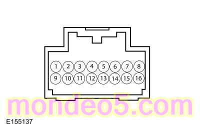 C218B-6 (component side)
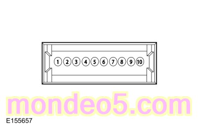 C C218C-5 (component side)