| 412-00 Climate Control System - General Information
|
2013 - 2014 Fusion
|
| Diagnosis and Testing
|
Procedure revision date:
07/10/2013
|
Climate Control System - Vehicles With: Dual Automatic Temperature Control (DATC)
DTC Chart: Front Controls Interface Module (FCIM) - Dual Automatic Temperature Control (DATC)
Diagnostics in this manual assume a certain skill level and knowledge of Ford-specific diagnostic practices. For information
about these practices,
REFER to:
Diagnostic Methods
(100-00 General Information, Description and Operation).
Network Diagnostic Trouble Codes (DTCs) (U-codes) are often a result of intermittent concerns such as damaged wiring or low
battery voltage occurrences. Additionally, vehicle repair procedures, such as module reprogramming, often set network Diagnostic
Trouble Codes (DTCs). Replacing a module to resolve a network
is unlikely to resolve the concern. To prevent repeat network
concerns, inspect all network wiring, especially connectors. Test the vehicle battery.
REFER to:
Battery
(414-01 Battery, Mounting and Cables, Diagnosis and Testing).
- Dual Automatic Temperature Control (DATC)
CHART
|
DTC
|
Description
|
Action
|
|
B105A:12
|
Cabin Temperature Sensor Fan: Circuit Short To Battery
|
GO to Pinpoint Test N
|
|
B105A:14
|
Cabin Temperature Sensor Fan: Circuit Short To Ground or Open
|
GO to Pinpoint Test N
|
|
B1081:07
|
Left Temperature Damper Motor: Mechanical Failure
|
INSPECT for a binding or a damaged linkage or door. REPAIR as necessary. If no condition is found, INSTALL a new driver side
temperature door actuator.
REFER to:
Driver Side Temperature Door Actuator
(412-00 Climate Control System - General Information, Removal and Installation).
.
|
|
B1081:11
|
Left Temperature Damper Motor: Circuit Short To Ground
|
GO to Pinpoint Test I
|
|
B1081:12
|
Left Temperature Damper Motor: Circuit Short To Battery
|
GO to Pinpoint Test I
|
|
B1081:13
|
Left Temperature Damper Motor: Circuit Open
|
GO to Pinpoint Test I
|
|
B1082:07
|
Right Temperature Damper Motor: Mechanical Failure
|
INSPECT for a binding or a damaged linkage or door. REPAIR as necessary. If no condition is found, INSTALL a new passenger
side temperature door actuator.
REFER to:
Passenger Side Temperature Door Actuator
(412-00 Climate Control System - General Information, Removal and Installation).
|
|
B1082:11
|
Right Temperature Damper Motor: Circuit Short To Ground
|
GO to Pinpoint Test J
|
|
B1082:12
|
Right Temperature Damper Motor: Circuit Short To Battery
|
GO to Pinpoint Test J
|
|
B1082:13
|
Right Temperature Damper Motor: Circuit Open
|
GO to Pinpoint Test J
|
|
B1083:07
|
Recirculation Damper Motor: Mechanical Failure
|
INSPECT for a binding or a damaged linkage or door. REPAIR as necessary. If no condition is found, INSTALL a new air inlet
mode door actuator.
REFER to:
Air Inlet Door Actuator
(412-00 Climate Control System - General Information, Removal and Installation).
|
|
B1083:11
|
Recirculation Damper Motor: Circuit Short To Ground
|
GO to Pinpoint Test D
|
|
B1083:12
|
Recirculation Damper Motor: Circuit Short To Battery
|
GO to Pinpoint Test D
|
|
B1083:13
|
Recirculation Damper Motor: Circuit Open
|
GO to Pinpoint Test D
|
|
B1086:07
|
Air Distribution Damper Motor: Mechanical Failure
|
INSPECT for a binding or a damaged linkage or door. REPAIR as necessary. If no condition is found, INSTALL a new air distribution
door actuator.
REFER to:
Air Distribution Door Actuator
(412-00 Climate Control System - General Information, Removal and Installation).
|
|
B1086:11
|
Air Distribution Damper Motor: Circuit Short To Ground
|
GO to Pinpoint Test E
|
|
B1086:12
|
Air Distribution Damper Motor: Circuit Short To Battery
|
GO to Pinpoint Test E
|
|
B1086:13
|
Air Distribution Damper Motor: Circuit Open
|
GO to Pinpoint Test E
|
|
B10AF:11
|
Blower Fan Relay: Circuit Short To Ground
|
GO to Pinpoint Test K
|
|
B10AF:12
|
Blower Fan Relay: Circuit Short To Battery
|
GO to Pinpoint Test L
|
|
B10AF:13
|
Blower Fan Relay: Circuit Open
|
GO to Pinpoint Test L
|
|
B10B3:11
|
Right Panel Air Discharge Temperature: Circuit Short To Ground
|
GO to Pinpoint Test M
|
|
B10B3:15
|
Right Panel Air Discharge Temperature: Circuit Short To Battery or Open
|
GO to Pinpoint Test M
|
|
B10B4:11
|
Right Floor Air Discharge Temperature: Circuit Short To Ground
|
GO to Pinpoint Test M
|
|
B10B4:15
|
Right Floor Air Discharge Temperature: Circuit Short To Battery or Open
|
GO to Pinpoint Test M
|
|
B10B5:11
|
Left Panel Air Discharge Temperature: Circuit Short To Ground
|
GO to Pinpoint Test M
|
|
B10B5:15
|
Left Panel Air Discharge Temperature: Circuit Short To Battery or Open
|
GO to Pinpoint Test M
|
|
B10B6:11
|
Left Floor Air Discharge Temperature: Circuit Short To Ground
|
GO to Pinpoint Test M
|
|
B10B6:15
|
Left Floor Air Discharge Temperature: Circuit Short To Ground
|
GO to Pinpoint Test M
|
|
B10B8:63
|
Push Buttons: Circuit / Component Protection Time-Out
|
-
Buttons held too long may set this
. ATTEMPT to clean buttons. CLEAR the Diagnostic Trouble Codes (DTCs) and REPEAT the self-test. If the
does not return, IGNORE the
and CONTINUE diagnosing other Diagnostic Trouble Codes (DTCs) or symptoms. If the
returns, INSTALL a new
.
-
For vehicles equipped with Sony® Audio System,
REFER to:
Information and Entertainment System
(415-00C Information and Entertainment System - General Information - Vehicles With: AM/FM/CD/SYNC/Sony Audio System, Diagnosis and Testing).
-
For vehicles equipped with Touchscreen Display,
REFER to:
Information and Entertainment System
(415-00B Information and Entertainment System - General Information - Vehicles With: AM/FM/CD/SYNC/Touchscreen Display, Diagnosis and Testing).
-
For all other audio systems,
REFER to:
Information and Entertainment System
(415-00A Information and Entertainment System - General Information - Vehicles With: AM/FM/CD/SYNC, Diagnosis and Testing).
|
|
B10B9:12
|
Blower Control: Circuit Short To Battery
|
|
|
B10B9:14
|
Blower Control: Circuit Short To Ground or Open
|
|
|
B11E5:11
|
Left HVAC Damper Position Sensor: Circuit Short To Ground
|
GO to Pinpoint Test I
|
|
B11E5:15
|
Left HVAC Damper Position Sensor: Circuit Short To Battery or Open
|
GO to Pinpoint Test I
|
|
B11E6:11
|
Right HVAC Damper Position Sensor: Circuit Short To Ground
|
GO to Pinpoint Test J
|
|
B11E6:15
|
Right HVAC Damper Position Sensor: Circuit Short To Battery or Open
|
GO to Pinpoint Test J
|
|
B11E7:11
|
Air Distribution Damper Position Sensor: Circuit Short To Ground
|
GO to Pinpoint Test E
|
|
B11E7:15
|
Air Distribution Damper Position Sensor: Circuit Short To Battery or Open
|
GO to Pinpoint Test E
|
|
B11F0:11
|
Air Intake Damper Position Sensor: Circuit Short To Ground
|
GO to Pinpoint Test D
|
|
B11F0:15
|
Air Intake Damper Position Sensor: Circuit Short To Battery or Open
|
GO to Pinpoint Test D
|
|
B1A61:11
|
Cabin Temperature Sensor: Circuit Short To Ground
|
GO to Pinpoint Test N
|
|
B1A61:15
|
Cabin Temperature Sensor: Circuit Short To Battery or Open
|
GO to Pinpoint Test N
|
|
B1A63:11
|
Right Solar Sensor: Circuit Short To Ground
|
GO to Pinpoint Test O
|
|
B1A63:15
|
Right Solar Sensor: Circuit Short To Battery or Open
|
GO to Pinpoint Test O
|
|
B1A64:11
|
Left Solar Sensor: Circuit Short To Ground
|
GO to Pinpoint Test O
|
|
B1A64:15
|
Left Solar Sensor: Circuit Short To Battery or Open
|
GO to Pinpoint Test O
|
|
B1A69:11
|
Humidity Sensor: Circuit Short To Ground
|
GO to Pinpoint Test N
|
|
B1A69:15
|
Humidity Sensor: Circuit Short To Battery or Open
|
GO to Pinpoint Test N
|
|
B1B71:11
|
Evaporator Temperature Sensor: Circuit Short To Ground
|
GO to Pinpoint Test P
|
|
B1B71:15
|
Evaporator Temperature Sensor: Circuit Short To Battery or Open
|
GO to Pinpoint Test P
|
|
C1B14:11
|
Sensor Supply Voltage A: Circuit Short To Ground
|
GO to Pinpoint Test Q
|
|
C1B14:12
|
Sensor Supply Voltage A: Circuit Short To Battery
|
GO to Pinpoint Test Q
|
|
All Other
Diagnostic Trouble Codes (DTCs) not listed in this chart
|
—
|
-
For vehicles equipped with Sony® Audio System,
REFER to:
Information and Entertainment System
(415-00C Information and Entertainment System - General Information - Vehicles With: AM/FM/CD/SYNC/Sony Audio System, Diagnosis and Testing).
-
For vehicles equipped with Touchscreen Display,
REFER to:
Information and Entertainment System
(415-00B Information and Entertainment System - General Information - Vehicles With: AM/FM/CD/SYNC/Touchscreen Display, Diagnosis and Testing).
-
For all other audio systems,
REFER to:
Information and Entertainment System
(415-00A Information and Entertainment System - General Information - Vehicles With: AM/FM/CD/SYNC, Diagnosis and Testing).
|
DTC Chart: Powertrain Control Module (PCM)
Diagnostics in this manual assume a certain skill level and knowledge of Ford-specific diagnostic practices. For information
about these practices,
REFER to:
Diagnostic Methods
(100-00 General Information, Description and Operation).
Powertrain Control Module (PCM) DTC Chart
Symptom Chart(s)
Symptom Chart: Climate Control - Dual Automatic Temperature Control (DATC)
Diagnostics in this manual assume a certain skill level and knowledge of Ford-specific diagnostic practices. For information
about these practices,
REFER to:
Diagnostic Methods
(100-00 General Information, Description and Operation).
Symptom Chart
|
Condition
|
Possible Sources
|
Actions
|
|
A module does not communicate with the diagnostic scan tool
|
-
Fuse(s)
-
Wiring, terminals or connectors
-
|
REFER to:
Communications Network
(418-00 Module Communications Network, Diagnosis and Testing).
|
|
Unable To Duplicate The Customer Concern And No Diagnostic Trouble Codes (DTCs) Present
|
Refer to Pinpoint Test
|
GO to Pinpoint Test C
|
|
functions are inoperative/do not operate correctly from touchscreen only
|
|
REFER to:
Information and Entertainment System
(415-00B Information and Entertainment System - General Information - Vehicles With: AM/FM/CD/SYNC/Touchscreen Display, Diagnosis and Testing).
|
|
Reduced outlet airflow
|
Refer to Pinpoint Test
|
GO to Pinpoint Test H
|
|
The air inlet door is inoperative
|
Refer to Pinpoint Test
|
GO to Pinpoint Test D
|
|
Incorrect or erratic direction of airflow from outlets
|
Refer to Pinpoint Test
|
GO to Pinpoint Test E
|
|
Insufficient, erratic or no heat
|
Refer to Pinpoint Test
|
GO to Pinpoint Test F
|
|
Insufficient heat in Auto Start-Stop mode only
|
Refer to Pinpoint Test
|
GO to Pinpoint Test R
|
|
The
is inoperative
|
Refer to Pinpoint Test
|
GO to Pinpoint Test G
|
|
The
is always on —
mode always commanded ON
|
Refer to Pinpoint Test
|
GO to Pinpoint Test H
|
|
Temperature control is inoperative/does not operate correctly —
|
Refer to Pinpoint Test
|
GO to Pinpoint Test I
|
|
Temperature control is inoperative/does not operate correctly —
|
Refer to Pinpoint Test
|
GO to Pinpoint Test J
|
|
The blower motor is inoperative
|
Refer to Pinpoint Test
|
GO to Pinpoint Test K
|
|
The blower motor does not operate correctly
|
Refer to Pinpoint Test
|
GO to Pinpoint Test L
|
|
Insufficient
cooling
|
Improper refrigerant level
|
CARRY OUT the refrigerant system tests.
REFER to:
Refrigerant System Tests
(412-00 Climate Control System - General Information, General Procedures).
If OK, DIAGNOSE for a temperature door actuator not operating correctly.
|
|
Temperature door actuator
|
|
|
pressure relief valve discharging
|
pressure relief valve
|
-
CHECK the high side system pressure.
REFER to:
Specifications
(412-00 Climate Control System - General Information, Specifications).
If the pressure is below the
pressure relief valve open pressure, INSTALL a new
Compressor.
-
For 1.5L,
REFER to:
Air Conditioning (A/C) Compressor - 1.5L EcoBoost (118kW/160PS)
(412-00 Climate Control System - General Information, Removal and Installation).
-
For 1.6L,
REFER to:
Air Conditioning (A/C) Compressor - 1.6L EcoBoost (132kW/180PS) - Sigma
(412-00 Climate Control System - General Information, Removal and Installation).
-
For 2.0L,
REFER to:
Air Conditioning (A/C) Compressor - 2.0L EcoBoost (184kW/250PS) - MI4
(412-00 Climate Control System - General Information, Removal and Installation).
-
For 2.5L,
REFER to:
Air Conditioning (A/C) Compressor - 2.5L Duratec (125kW/170PS)
(412-00 Climate Control System - General Information, Removal and Installation).
|
|
High system pressure
|
CHECK the high side system pressure.
REFER to:
Specifications
(412-00 Climate Control System - General Information, Specifications).
If the system pressure is above the
pressure relief valve open pressure, REPAIR the
system for a restriction.
|
Symptom Chart: Noise, Vibration, and Harshness (NVH)
Diagnostics in this manual assume a certain skill level and knowledge of Ford-specific diagnostic practices. For information
about these practices,
REFER to:
Diagnostic Methods
(100-00 General Information, Description and Operation).
Symptom Chart
|
Condition
|
Possible Sources
|
Actions
|
|
Noisy
compressor
|
compressor bearing worn
|
|
|
Excessive hissing from the plenum when the
is on
|
Incorrect
refrigerant level
|
CHECK the
refrigerant level
REFER to:
Refrigerant System Tests
(412-00 Climate Control System - General Information, General Procedures).
|
Pinpoint Test(s)
P0532, P0533
Refer to Wiring Diagrams Cell 55 for schematic and connector information.
Normal operation and Fault Conditions
The
pressure transducer receives a ground from the
. A 5-volt reference voltage is supplied to the
pressure transducer from the
. The
pressure transducer then sends a voltage to the
to indicate the
pressure.
DTC Fault Trigger Conditions
|
DTC
|
Description
|
Fault Trigger Conditions
|
|
P0532
|
A/C Refrigerant Pressure Sensor "A" Circuit Low
|
The
pressure transducer inputs a feedback voltage to the
. This
sets if the feedback voltage is less than 0.26 volt for at least 2 seconds and the ambient air temperature is greater than
0°C (32°F).
|
|
P0533
|
A/C Refrigerant Pressure Sensor "A" Circuit High
|
The
pressure transducer inputs a feedback voltage to the
. This
sets if the feedback voltage is greater than 4.95 volts for at least 2 seconds and the ambient air temperature is greater
than 0°C (32°F).
|
Possible Sources
-
Wiring, terminals or connectors
-
pressure transducer
-
Visual Inspection and Diagnostic Pre-checks
-
Inspect for loose or corroded
and
pressure transducer connections.
PINPOINT TEST A : P0532, P0533
| NOTICE:
Use the correct probe adapter(s) when making measurements. Failure to use the correct probe adapter(s) may damage the connector.
|
| A1
COMPARE THE PCM (POWERTRAIN CONTROL MODULE)
PRESSURE SENSOR (ACP_PRESS) PID (PARAMETER IDENTIFICATION)
WITH THE MANIFOLD GAUGE SET READINGS
|
-
Allow the
system to stabilize to the outside ambient temperature.
-
Using a diagnostic scan tool, view
Parameter Identifications (PIDs).
-
With the manifold gauge set connected, compare the pressure readings of the manifold gauge set and the
ACP_PRESS
.
Are the pressure values of the manifold gauge set and the
within +/-15 psi?
| Yes
|
IGNORE the Diagnostic Trouble Codes (DTCs). REFER to the Symptom Chart in this section.
|
|
| A2
CHECK THE PCM (POWERTRAIN CONTROL MODULE)
REFERENCE VOLTAGE CIRCUIT
|
-
Disconnect
pressure transducer C1260
.
-
Measure:
|
Positive Lead
|
Measurement / Action
|
Negative Lead
|
|
C1260-3
|

|
Ground
|
Is the voltage between 4.7 and 5.1 volts?
| No
|
If the voltage is less than 4.7 volts, GO to
A3
If the voltage is greater than 5.1 volts, REPAIR the circuit for a short to voltage.
|
|
| A3
CHECK THE REFERENCE VOLTAGE CIRCUIT FOR A SHORT TO GROUND
|
-
Disconnect
1.5L C1915B, 1.6L C1232B, 2.0L C1381B or 2.5L C1551B
.
-
Measure:
|
Positive Lead
|
Measurement / Action
|
Negative Lead
|
|
C1260-3
|

|
Ground
|
Is the resistance greater than 10,000 ohms?
|
| A4
CHECK THE REFERENCE VOLTAGE CIRCUIT FOR AN OPEN
|
-
Measure:
1.5L
|
Positive Lead
|
Measurement / Action
|
Negative Lead
|
|
C1260-3
|
|
C1915B-11
|
1.6L
|
Positive Lead
|
Measurement / Action
|
Negative Lead
|
|
C1260-3
|
|
C1232B-11
|
2.0L
|
Positive Lead
|
Measurement / Action
|
Negative Lead
|
|
C1260-3
|
|
C1381B-11
|
2.5L
|
Positive Lead
|
Measurement / Action
|
Negative Lead
|
|
C1260-3
|
|
C1551B-52
|
Is the resistance less than 3 ohms?
|
| A5
CHECK THE SIGNAL RETURN CIRCUIT
|
-
Measure:
|
Positive Lead
|
Measurement / Action
|
Negative Lead
|
|
C1260-1
|
|
C1260-3
|
Is the voltage between 4.7 and 5.1 volts?
| Yes
|
If diagnosing
P0532, GO to
A8
If diagnosing
P0533, GO to
A11
|
|
| A6
CHECK THE SIGNAL RETURN CIRCUIT FOR A SHORT TO VOLTAGE
|
-
Measure:
|
Positive Lead
|
Measurement / Action
|
Negative Lead
|
|
C1260-1
|
|
Ground
|
Is any voltage present?
|
| A7
CHECK THE SIGNAL RETURN CIRCUIT FOR AN OPEN
|
-
Disconnect
1.5L C1915B, 1.6L C1232B, 2.0L C1381B or 2.5L C1551B
.
-
Measure:
1.5L
|
Positive Lead
|
Measurement / Action
|
Negative Lead
|
|
C1260-1
|
|
C1915B-18
|
1.6L
|
Positive Lead
|
Measurement / Action
|
Negative Lead
|
|
C1260-1
|
|
C1232B-18
|
2.0L
|
Positive Lead
|
Measurement / Action
|
Negative Lead
|
|
C1260-1
|
|
C1381B-18
|
2.5L
|
Positive Lead
|
Measurement / Action
|
Negative Lead
|
|
C1260-1
|
|
C1551B-56
|
Is the resistance less than 3 ohms?
|
| A8
CHECK THE PCM (POWERTRAIN CONTROL MODULE)
A/C (AIR CONDITIONING)
PRESSURE SENSOR (ACP_V) PID (PARAMETER IDENTIFICATION)
WITH THE A/C (AIR CONDITIONING)
PRESSURE TRANSDUCER SHORTED
|
-
Connect a fused jumper wire between:
|
Positive Lead
|
Measurement / Action
|
Negative Lead
|
|
C1260-2
|

|
C1260-3
|
-
Using a diagnostic scan tool, view
Parameter Identifications (PIDs).
-
Monitor the ACP_V
voltage.
Does the
voltage display between 4.7 and 5.1 volts?
| No
|
REMOVE the fused jumper wire. GO to
A9
|
|
| A9
CHECK THE A/C (AIR CONDITIONING)
PRESSURE TRANSDUCER FEEDBACK CIRCUIT FOR A SHORT TO THE SIGNAL RETURN CIRCUIT
|
-
Disconnect
1.5L C1915B, 1.6L C1232B, 2.0L C1381B or 2.5L C1551B
.
-
Measure:
|
Positive Lead
|
Measurement / Action
|
Negative Lead
|
|
C1260-2
|
|
C1260-1
|
Is the resistance greater than 10,000 ohms?
|
| A10
CHECK THE A/C (AIR CONDITIONING)
PRESSURE TRANSDUCER FEEDBACK CIRCUIT FOR AN OPEN
|
-
Measure:
1.5L
|
Positive Lead
|
Measurement / Action
|
Negative Lead
|
|
C1260-2
|
|
C1915B-52
|
1.6L
|
Positive Lead
|
Measurement / Action
|
Negative Lead
|
|
C1260-2
|
|
C1232B-52
|
2.0L
|
Positive Lead
|
Measurement / Action
|
Negative Lead
|
|
C1260-2
|
|
C1381B-52
|
2.5L
|
Positive Lead
|
Measurement / Action
|
Negative Lead
|
|
C1260-2
|
|
C1551B-31
|
Is the resistance less than 3 ohms?
|
| A11
CHECK THE A/C (AIR CONDITIONING)
PRESSURE TRANSDUCER
|
-
Using a diagnostic scan tool, view
Parameter Identifications (PIDs).
-
Monitor the
pressure sensor (ACP_V)
voltage.
Does the
voltage display 0 volts?
|
| A12
CHECK THE A/C (AIR CONDITIONING)
PRESSURE TRANSDUCER FEEDBACK CIRCUIT FOR VOLTAGE
|
-
Measure:
|
Positive Lead
|
Measurement / Action
|
Negative Lead
|
|
C1260-2
|
|
Ground
|
Is any voltage present?
|
| A13
CHECK THE A/C (AIR CONDITIONING)
PRESSURE TRANSDUCER FEEDBACK CIRCUIT FOR A SHORT TO VOLTAGE
|
-
Disconnect
1.5L C1915B, 1.6L C1232B, 2.0L C1381B or 2.5L C1551B
.
-
Measure:
|
Positive Lead
|
Measurement / Action
|
Negative Lead
|
|
C1260-2
|
|
Ground
|
Is any voltage present?
| No
|
REPAIR feedback circuit for a short to signal return circuit.
|
|
| A14
CHECK FOR CORRECT PCM (POWERTRAIN CONTROL MODULE)
OPERATION
|
-
Disconnect and inspect all
connectors.
-
Repair:
-
corrosion (install new connector or terminals – clean module pins)
-
damaged or bent pins – install new terminals/pins
-
pushed-out pins – install new pins as necessary
-
Connect the
connectors. Make sure they seat and latch correctly.
-
Operate the system and determine if the concern is still present.
Is the concern still present?
| Yes
|
CHECK
for any applicable Technical Service Bulletins (TSBs). If a
exists for this concern, DISCONTINUE this test and FOLLOW
instructions. If no Technical Service Bulletins (TSBs) address this concern, INSTALL a new
.
For 1.5L,
REFER to:
Powertrain Control Module (PCM)
(303-14A Electronic Engine Controls - 1.5L EcoBoost (118kW/160PS), Removal and Installation).
For 1.6L,
REFER to:
Powertrain Control Module (PCM)
(303-14B Electronic Engine Controls - 1.6L EcoBoost (132kW/180PS) - Sigma, Removal and Installation).
For 2.0L,
REFER to:
Powertrain Control Module (PCM)
(303-14C Electronic Engine Controls - 2.0L EcoBoost (184kW/250PS) - MI4, Removal and Installation).
For 2.5L,
REFER to:
Powertrain Control Module (PCM)
(303-14D Electronic Engine Controls - 2.5L Duratec (125kW/170PS), Removal and Installation).
|
| No
|
The system is operating correctly at this time. The concern may have been caused by a loose or corroded connector. ADDRESS
the root cause of any connector or pin issues.
|
|
P0645
Refer to Wiring Diagrams Cell 55 for schematic and connector information.
Normal Operation and Fault Conditions
Voltage is provided to the
clutch relay coil. When
is requested and
line pressures allow, a ground is provided to the
clutch relay coil from the
, energizing the
clutch relay.
DTC Fault Trigger Conditions
|
DTC
|
Description
|
Fault Trigger Conditions
|
|
P0645
|
A/C Clutch Relay Control Circuit
|
The
sets when the
grounds the relay circuit and more voltage than expected is detected on the relay circuit. The
also sets when the relay circuit is off and no voltage is detected on the relay circuit. The
expects to detect voltage coming through the relay coil to the relay circuit when it is not grounding it.
|
Possible Sources
-
Wiring, terminals or connectors
-
clutch relay
-
Visual Inspection and Diagnostic Pre-checks
PINPOINT TEST B : P0645
| NOTICE:
Use the correct probe adapter(s) from the Flex Probe Kit when taking measurements. Failure to use the correct probe adapter(s)
may damage the connector.
|
| B1
CHECK THE VOLTAGE TO THE A/C (AIR CONDITIONING)
CLUTCH RELAY COIL VOLTAGE SUPPLY CIRCUIT FOR AN OPEN
|
-
Measure:
|
Positive Lead
|
Measurement / Action
|
Negative Lead
|
 Pin 2
Pin 2
|
|
Ground
|
Is the voltage greater than 11 volts?
|
| B2
SUBSTITUTE A KNOWN GOOD RELAY FOR THE A/C (AIR CONDITIONING)
CLUTCH RELAY
|
-
Substitute a known good relay for the
clutch relay.
-
Using a diagnostic scan tool, perform
self-test.
Is
P0645:00 still present?
| No
|
INSTALL a new
clutch relay.
|
|
| B3
CHECK THE A/C (AIR CONDITIONING)
CLUTCH RELAY CONTROL CIRCUIT FOR A SHORT TO VOLTAGE
|
-
Disconnect
1.5L C1915B, 1.6L C1232B, 2.0L C1381B or 2.5L C1551B
.
-
Measure:
|
Positive Lead
|
Measurement / Action
|
Negative Lead
|
|
Pin 1
|
|
Ground
|
Is any voltage present?
|
| B4
CHECK THE A/C (AIR CONDITIONING)
CLUTCH RELAY CONTROL CIRCUIT FOR A SHORT TO GROUND
|
-
Measure:
|
Positive Lead
|
Measurement / Action
|
Negative Lead
|
|
Pin 1
|
|
Ground
|
Is the resistance greater than 10,000 ohms?
|
| B5
CHECK THE A/C (AIR CONDITIONING)
CLUTCH RELAY CONTROL CIRCUIT FOR AN OPEN
|
-
Measure:
1.5L
|
Positive Lead
|
Measurement / Action
|
Negative Lead
|
|
Pin 1
|
|
C1915B-2
|
1.6L
|
Positive Lead
|
Measurement / Action
|
Negative Lead
|
|
Pin 1
|
|
C1232B-2
|
2.0L
|
Positive Lead
|
Measurement / Action
|
Negative Lead
|
|
Pin 1
|
|
C1381B-2
|
2.5L
|
Positive Lead
|
Measurement / Action
|
Negative Lead
|
|
Pin 1
|
|
C1551B-12
|
Is the resistance less than 3 ohms?
|
| B6
CHECK FOR CORRECT PCM (POWERTRAIN CONTROL MODULE)
OPERATION
|
-
Disconnect and inspect all the
connectors.
-
Repair:
-
corrosion (install new connector or terminals – clean module pins)
-
damaged or bent pins – install new terminals/pins
-
pushed-out pins – install new pins as necessary
-
Connect the
connectors. Make sure they seat and latch correctly.
-
Operate the system and determine if the concern is still present.
Is the concern still present?
| Yes
|
CHECK
for any applicable Technical Service Bulletins (TSBs). If a
exists for this concern, DISCONTINUE this test and FOLLOW
instructions. If no Technical Service Bulletins (TSBs) address this concern, INSTALL a new
.
For 1.5L,
REFER to:
Powertrain Control Module (PCM)
(303-14A Electronic Engine Controls - 1.5L EcoBoost (118kW/160PS), Removal and Installation).
For 1.6L,
REFER to:
Powertrain Control Module (PCM)
(303-14B Electronic Engine Controls - 1.6L EcoBoost (132kW/180PS) - Sigma, Removal and Installation).
For 2.0L,
REFER to:
Powertrain Control Module (PCM)
(303-14C Electronic Engine Controls - 2.0L EcoBoost (184kW/250PS) - MI4, Removal and Installation).
For 2.5L,
REFER to:
Powertrain Control Module (PCM)
(303-14D Electronic Engine Controls - 2.5L Duratec (125kW/170PS), Removal and Installation).
|
| No
|
The system is operating correctly at this time. The concern may have been caused by a loose or corroded connector. ADDRESS
the root cause of any connector or pin issues.
|
|
Unable To Duplicate The Customer Concern And No Diagnostic Trouble Codes (DTCs) Present
This diagnostic procedure tests the functions of the
system and identifies the correct
symptom pinpoint test.
Normal Operation and Fault Conditions
System Operation
REFER to:
Climate Control System - Vehicles With: Dual Automatic Temperature Control (DATC) - System Operation and Component Description
(412-00 Climate Control System - General Information, Description and Operation).
PINPOINT TEST C : UNABLE TO DUPLICATE THE CUSTOMER CONCERN AND NO DIAGNOSTIC TROUBLE CODES (DTCS) PRESENT
| C1
CHECK THE PCM (POWERTRAIN CONTROL MODULE)
FOR DIAGNOSTIC TROUBLE CODES (DTCS)
|
-
Using a scan tool, perform
self-test.
Are any climate control related Diagnostic Trouble Codes (DTCs) present?
| Yes
|
REFER to the
chart in this section.
|
|
| C2
CHECK THE FCIM (FRONT CONTROLS INTERFACE MODULE)
FOR DIAGNOSTIC TROUBLE CODES (DTCS)
|
-
Using a diagnostic scan tool, perform
self-test.
Are any Diagnostic Trouble Codes (DTCs) present?
| Yes
|
REFER to the
chart in this section.
|
|
| C3
CHECK THE BLOWER MOTOR OPERATION
|
-
Observe blower motor operation and select each blower motor speed.
Does the blower motor operate in all ranges?
|
| C4
CHECK AIRFLOW OPERATION
|
-
Select the highest blower motor setting.
-
While observing the airflow, select each of the airflow positions (panel, panel/floor, floor, floor/defrost, defrost).
Is the airflow directed to the correct outlets?
|
| C5
VERIFY TEMPERATURE CONTROL OPERATION
|
-
Start the vehicle and allow it to reach normal operating temperature.
-
With the
off, select panel mode.
-
Change the driver and passenger temperature settings from the coldest to the warmest and back to the coldest.
Does the temperature change between very warm to cool?
|
| C6
VERIFY THE AIR CONDITIONING COMPRESSOR DOES NOT ENGAGE WITH A/C (AIR CONDITIONING)
OFF
|
-
With the engine running and the
off, select panel mode.
-
Select the coldest temperature setting.
Is the outlet temperature close to ambient air temperature?
|
| C7
VERIFY THE A/C (AIR CONDITIONING)
COMPRESSOR IS OPERATIONAL IN THE A/C (AIR CONDITIONING)
MODE
|
-
Make sure the ambient air temperature is above 2°C (36°F).
-
With the engine running, select panel mode.
-
Press the
button (indicator on).
Is the
compressor operational when the panel and
button (indicator on) is pressed?
|
| C8
CHECK THE RECIRCULATED AIR OPERATION
|
-
With the engine running, press the recirculated air button (indicator off).
-
Select the highest blower motor setting.
-
Press the recirculated air button (indicator on).
Does the airflow noise increase when the recirculated air mode is selected (indicator on)?
|
| C9
CHECK THE FCIM (FRONT CONTROLS INTERFACE MODULE)
LEFT DISCHARGE FLOOR TEMPERATURE (LDFTEMP) PID (PARAMETER IDENTIFICATION)
|
-
Using a diagnostic scan tool, view the
Parameter Identifications (PIDs).
Is the temperature coming out of the driver footwell vent similar to the
?
|
| C10
CHECK THE FCIM (FRONT CONTROLS INTERFACE MODULE)
LEFT DISCHARGE PANEL TEMPERATURE (LDPT) PID (PARAMETER IDENTIFICATION)
|
-
Using a diagnostic scan tool, view the
Parameter Identifications (PIDs).
Is the temperature coming out of the driver side register similar to the
?
|
| C11
CHECK THE FCIM (FRONT CONTROLS INTERFACE MODULE)
DISCHARGE AIR TEMPERATURE RIGHT FLOOR (AIRTEMP_RF) PID (PARAMETER IDENTIFICATION)
|
-
Using a diagnostic scan tool, view the
Parameter Identifications (PIDs).
Is the temperature coming out of the passenger footwell vent similar to the
?
|
| C12
CHECK THE FCIM (FRONT CONTROLS INTERFACE MODULE)
DISCHARGE AIR TEMPERATURE RIGHT PANEL (AIRTEMP_RP) PID (PARAMETER IDENTIFICATION)
|
-
Using a scan tool view the
Parameter Identifications (PIDs).
Is the temperature coming out of the passenger side register similar to the
?
|
| C13
CHECK THE FCIM (FRONT CONTROLS INTERFACE MODULE)
INTERIOR TEMPERATURE SENSOR (INT_TEMP) PID (PARAMETER IDENTIFICATION)
|
-
Using a scan tool view the
Parameter Identifications (PIDs).
Is the air temperature at the cabin temperature sensor similar to the
?
|
| C14
CHECK THE TOUCHSCREEN CONTROLS OPERATION
|
-
Using the touchscreen controls, select each climate control function.
-
Using the touchscreen controls, select each audio control function.
Do all touchscreen controls operate?
| Yes
|
The system is operating correctly.
|
| No
|
REFER to:
Information and Entertainment System
(415-00B Information and Entertainment System - General Information - Vehicles With: AM/FM/CD/SYNC/Touchscreen Display, Diagnosis and Testing).
|
|
The Air Inlet Blend Door Is Inoperative
Refer to Wiring Diagrams Cell 55 for schematic and connector information.
Normal Operation and Fault Conditions
To rotate the air inlet blend door actuator, the
supplies voltage and ground to the air inlet blend door actuator through the door actuator motor circuits. To reverse the
air inlet blend door actuator rotation, the
reverses the voltage and ground circuits. The air inlet blend door actuator feedback resistors are supplied a ground from
the
by the air inlet blend door actuator return circuits and a 5-volt reference voltage on the air inlet blend door actuator
reference circuits. The
reads the voltage on the air inlet blend door actuator feedback circuits to determine the air inlet blend door actuator position
by the position of the actuator feedback resistor wiper arm.
During an actuator calibration cycle, the
drives the air inlet blend door until the door reaches both internal stops in the
case. If the air inlet mode door is temporarily obstructed or binding during a calibration cycle, the
may interpret this as the actual end of travel for the door. When this condition occurs and the
commands the actuator to its end of travel, the air intake may not be from the expected source.
DTC Fault Trigger Conditions
|
DTC
|
Description
|
Fault Trigger Conditions
|
|
B1083:11
|
Recirculation Damper Motor: Circuit Short To Ground
|
This
sets when the module senses lower than expected voltage on an actuator motor circuit when voltage is applied to drive the
motor, indicating a short to ground.
|
|
B1083:12
|
Recirculation Damper Motor: Circuit Short To Battery
|
This
sets when the module senses higher than expected voltage on the actuator motor circuit when ground is applied to drive the
motor, indicating a short to voltage.
|
|
B1083:13
|
Recirculation Damper Motor: Circuit Open
|
This
sets when the module senses no voltage on the actuator motor circuit when ground is applied to drive the motor, indicating
a open circuit.
|
|
B11F0:11
|
Air Intake Damper Position Sensor: Circuit Short to Ground
|
This
sets when the module senses less than 1 volt on the actuator feedback circuit, indicating a short to ground.
|
|
B11F0:15
|
Air Intake Damper Position Sensor: Circuit Short to Battery or Open
|
This
sets when the module senses greater than 4 volts on the actuator feedback circuit, indicating an open circuit or a short
to voltage.
|
Possible Sources
-
Wiring, terminals or connectors
-
Air inlet blend door actuator
-
Air inlet blend door binding or stuck
-
PINPOINT TEST D : THE AIR INLET BLEND DOOR IS INOPERATIVE
| NOTICE:
Use the correct probe adapter(s) when making measurements. Failure to use the correct probe adapter(s) may damage the connector.
|
| D1
CHECK THE AIR INLET BLEND DOOR ACTUATOR CIRCUITS FOR A SHORT TO VOLTAGE
|
-
Disconnect Air Inlet Blend Door Actuator C289
.
-
Measure:
|
Positive Lead
|
Measurement / Action
|
Negative Lead
|
|
C289-1
|
|
Ground
|
|
C289-2
|
|
Ground
|
|
C289-3
|
|
Ground
|
|
C289-4
|
|
Ground
|
|
C289-6
|
|
Ground
|
Is there any voltage present?
|
| D2
CHECK THE AIR INLET BLEND DOOR ACTUATOR CIRCUITS FOR A SHORT TO GROUND
|
-
Measure:
|
Positive Lead
|
Measurement / Action
|
Negative Lead
|
|
C289-1
|
|
Ground
|
|
C289-2
|
|
Ground
|
|
C289-3
|
|
Ground
|
|
C289-4
|
|
Ground
|
|
C289-6
|
|
Ground
|
Are the resistances greater than 10,000 ohms?
|
| D3
CHECK THE AIR INLET BLEND DOOR ACTUATOR CIRCUITS FOR AN OPEN
|
-
Measure:
|
Positive Lead
|
Measurement / Action
|
Negative Lead
|
|
C289-1
|
|
C2402A-24
|
|
C289-2
|
|
C2402A-2
|
|
C289-3
|
|
C2402A-3
|
|
C289-4
|
|
C2402A-16
|
|
C289-6
|
|
C2402A-25
|
Are the resistances less than 3 ohms?
|
| D4
CHECK THE AIR INLET BLEND DOOR ACTUATOR CIRCUITS FOR A SHORT TOGETHER
|
-
Measure:
|
Positive Lead
|
Measurement / Action
|
Negative Lead
|
|
C289-1
|
|
C289-2
|
|
C289-1
|
|
C289-3
|
|
C289-1
|
|
C289-4
|
|
C289-1
|
|
C289-6
|
|
C289-2
|
|
C289-3
|
|
C289-2
|
|
C289-4
|
|
C289-2
|
|
C289-6
|
|
C289-3
|
|
C289-4
|
|
C289-3
|
|
C289-6
|
|
C289-4
|
|
C289-6
|
Are the resistances greater than 10,000 ohms?
| Yes
|
INSTALL a new air inlet blend door actuator.
REFER to:
Air Inlet Door Actuator
(412-00 Climate Control System - General Information, Removal and Installation).
TEST the system for normal operation. If the concern is still present, GO to
D5
|
|
| D5
CHECK FOR CORRECT FRONT CONTROLS INTERFACE MODULE OPERATION
|
-
Disconnect and inspect all the
connectors.
-
Repair:
-
corrosion (install new connector or terminals – clean module pins)
-
damaged or bent pins – install new terminals/pins
-
pushed-out pins – install new pins as necessary
-
Connect the
connectors. Make sure they seat and latch correctly.
-
Operate the system and determine if the concern is still present.
Is the concern still present?
| Yes
|
CHECK
for any applicable Technical Service Bulletins (TSBs). If a
exists for this concern, DISCONTINUE this test and FOLLOW
instructions. If no Technical Service Bulletins (TSBs) address this concern, INSTALL a new
.
For vehicles equipped with Sony® Audio System,
REFER to:
Front Controls Interface Module (FCIM)
(415-00C Information and Entertainment System - General Information - Vehicles With: AM/FM/CD/SYNC/Sony Audio System, Removal and Installation).
For vehicles equipped with Touchscreen Display,
REFER to:
Front Controls Interface Module (FCIM)
(415-00B Information and Entertainment System - General Information - Vehicles With: AM/FM/CD/SYNC/Touchscreen Display, Removal and Installation).
For all other audio systems,
REFER to:
Front Controls Interface Module (FCIM)
(415-00A Information and Entertainment System - General Information - Vehicles With: AM/FM/CD/SYNC, Removal and Installation).
|
| No
|
The system is operating correctly at this time. The concern may have been caused by a loose or corroded connector. ADDRESS
the root cause of any connector or pin issues.
|
|
Incorrect Or Erratic Direction Of Airflow From Outlets
Refer to Wiring Diagrams Cell 55 for schematic and connector information.
Normal Operation and Fault Conditions
To rotate the air distribution door actuator, the
supplies voltage and ground to the air distribution door actuator through the door actuator motor circuits. To reverse the
air distribution door actuator rotation, the
reverses the voltage and ground circuits. The air distribution door actuator feedback resistors are supplied a ground from
the
by the air distribution door actuator return circuits and a 5-volt reference voltage on the air distribution door actuator
reference circuits. The
reads the voltage on the air distribution door actuator feedback circuits to determine the air distribution door actuator
position by the position of the actuator feedback resistor wiper arm.
During an actuator calibration cycle, the
drives the air distribution door until the door reaches both internal stops in the
case. If the air distribution door is temporarily obstructed or binding during a calibration cycle, the
may interpret this as the actual end of travel for the door. When this condition occurs and the
commands the actuator to its end of travel, the airflow may not be from the expected outlets.
DTC Fault Trigger Conditions
|
DTC
|
Description
|
Fault Trigger Conditions
|
|
B1086:11
|
Air Distribution Damper Motor: Circuit Short to Ground
|
This
sets when the module senses no changes in the feedback circuit when motor movement is commanded and no motor electrical Diagnostic
Trouble Codes (DTCs) are present.
|
|
B1086:12
|
Air Distribution Damper Motor: Circuit Short to Battery
|
This
sets when the module senses no changes in the feedback circuit when motor movement is commanded and no motor electrical Diagnostic
Trouble Codes (DTCs) are present.
|
|
B1086:13
|
Air Distribution Damper Motor: Circuit Open
|
This
sets when the module senses no voltage on the actuator motor circuit when ground is applied to drive the motor, indicating
a open circuit.
|
|
B11E7:11
|
Air Distribution Damper Position Sensor: Circuit Short to ground
|
This
sets when the module senses less than 1 volt on the actuator feedback circuit, indicating a short to ground.
|
|
B11E7:15
|
Air Distribution Damper Position Sensor: Circuit Short to Battery or Open
|
This
sets when the module senses greater than 4 volts on the actuator feedback circuit, indicating an open circuit or a short
to voltage.
|
Possible Sources
-
Wiring, terminals or connectors
-
Air distribution door actuator
-
Air distribution door binding or stuck
-
PINPOINT TEST E : INCORRECT OR ERRATIC DIRECTION OF AIRFLOW FROM OUTLETS
| NOTICE:
Use the correct probe adapter(s) when making measurements. Failure to use the correct probe adapter(s) may damage the connector.
|
| E1
CHECK THE AIR DISTRIBUTION DOOR ACTUATOR CIRCUITS FOR A SHORT TO VOLTAGE
|
-
Disconnect Air distribution door actuator C236
.
-
Measure:
|
Positive Lead
|
Measurement / Action
|
Negative Lead
|
|
C236-1
|
|
Ground
|
|
C236-2
|
|
Ground
|
|
C236-3
|
|
Ground
|
|
C236-4
|
|
Ground
|
|
C236-6
|
|
Ground
|
Is there any voltage present?
|
| E2
CHECK THE AIR DISTRIBUTION DOOR ACTUATOR CIRCUITS FOR A SHORT TO GROUND
|
-
Measure:
|
Positive Lead
|
Measurement / Action
|
Negative Lead
|
|
C236-1
|
|
Ground
|
|
C236-2
|
|
Ground
|
|
C236-3
|
|
Ground
|
|
C236-4
|
|
Ground
|
|
C236-6
|
|
Ground
|
Are the resistances greater than 10,000 ohms?
|
| E3
CHECK THE AIR DISTRIBUTION DOOR ACTUATOR CIRCUITS FOR AN OPEN
|
-
Measure:
|
Positive Lead
|
Measurement / Action
|
Negative Lead
|
|
C236-1
|
|
C2402A-20
|
|
C236-2
|
|
C2402A-2
|
|
C236-3
|
|
C2402A-3
|
|
C236-4
|
|
C2402A-22
|
|
C236-6
|
|
C2402A-21
|
Are the resistances less than 3 ohms?
|
| E4
CHECK THE AIR DISTRIBUTION DOOR ACTUATOR CIRCUITS FOR A SHORT TOGETHER
|
-
Measure:
|
Positive Lead
|
Measurement / Action
|
Negative Lead
|
|
C236-1
|
|
C236-2
|
|
C236-1
|
|
C236-3
|
|
C236-1
|
|
C236-4
|
|
C236-1
|
|
C236-6
|
|
C236-2
|
|
C236-3
|
|
C236-2
|
|
C236-4
|
|
C236-2
|
|
C236-6
|
|
C236-3
|
|
C236-4
|
|
C236-3
|
|
C236-6
|
|
C236-4
|
|
C236-6
|
Are the resistances greater than 10,000 ohms?
| Yes
|
INSTALL a new air distribution blend door actuator,
REFER to:
Air Distribution Door Actuator
(412-00 Climate Control System - General Information, Removal and Installation).
TEST the system for normal operation. If the concern is still present, GO to
E5
|
|
| E5
CHECK FOR CORRECT FCIM (FRONT CONTROLS INTERFACE MODULE)
OPERATION
|
-
Disconnect and inspect all the
connectors.
-
Repair:
-
corrosion (install new connector or terminals – clean module pins)
-
damaged or bent pins – install new terminals/pins
-
pushed-out pins – install new pins as necessary
-
Connect the
connectors. Make sure they seat and latch correctly.
-
Operate the system and determine if the concern is still present.
Is the concern still present?
| Yes
|
CHECK
for any applicable Technical Service Bulletins (TSBs). If a
exists for this concern, DISCONTINUE this test and FOLLOW
instructions. If no Technical Service Bulletins (TSBs) address this concern, INSTALL a new
.
For vehicles equipped with Sony® Audio System,
REFER to:
Front Controls Interface Module (FCIM)
(415-00C Information and Entertainment System - General Information - Vehicles With: AM/FM/CD/SYNC/Sony Audio System, Removal and Installation).
For vehicles equipped with Touchscreen Display,
REFER to:
Front Controls Interface Module (FCIM)
(415-00B Information and Entertainment System - General Information - Vehicles With: AM/FM/CD/SYNC/Touchscreen Display, Removal and Installation).
For all other audio systems,
REFER to:
Front Controls Interface Module (FCIM)
(415-00A Information and Entertainment System - General Information - Vehicles With: AM/FM/CD/SYNC, Removal and Installation).
|
| No
|
The system is operating correctly at this time. The concern may have been caused by a loose or corroded connector. ADDRESS
the root cause of any connector or pin issues.
|
|
Insufficient, Erratic Or No Heat
Normal Operation and Fault Conditions
When the engine is at operating temperature hot coolant flows from the electric motor through the heater core and back to
the electric motor. Correct coolant temperatures are critical for good heater performance.
Possible Sources
-
Wiring, terminals or connectors
-
Temperature blend door actuator(s)
-
Heater core
Visual Inspection and Diagnostic Pre-checks
-
Inspect for low engine coolant level.
PINPOINT TEST F : INSUFFICIENT, ERRATIC OR NO HEAT
| F1
CHECK FOR CORRECT ENGINE COOLANT LEVEL
|
-
Check the engine coolant level.
Is the engine coolant at the correct level as indicated on the engine coolant recovery reservoir?
|
| F2
CHECK THE ENGINE COOLING SYSTEM FOR LEAKS
|
-
Pressure test the cooling system for leaks.
-
For 1.5L engine,
REFER to:
Engine Cooling
(303-03A Engine Cooling - 1.5L EcoBoost (118kW/160PS), Diagnosis and Testing).
-
For 1.6L engine,
REFER to:
Engine Cooling
(303-03B Engine Cooling - 1.6L EcoBoost (132kW/180PS) - Sigma, Diagnosis and Testing).
-
For 2.0L engine,
REFER to:
Engine Cooling
(303-03C Engine Cooling - 2.0L EcoBoost (184kW/250PS) - MI4, Diagnosis and Testing).
-
For 2.5L engine,
REFER to:
Engine Cooling
(303-03D Engine Cooling - 2.5L Duratec (125kW/170PS), Diagnosis and Testing).
Does the engine cooling system leak?
| Yes
|
REPAIR the engine coolant leak. TEST the system for normal operation.
|
|
| F3
CHECK FOR COOLANT FLOW TO THE HEATER CORE
|
-
Run the motor until it reaches normal operating temperature. Select the floor position on the control assembly. Set the temperature
control to full warm and the blower to the lowest setting.
-
Using a suitable temperature measuring device, check the heater core inlet hose to see if it is hot.
Is the heater core inlet hose hot?
| No
|
For 1.5L engine,
REFER to:
Engine Cooling
(303-03A Engine Cooling - 1.5L EcoBoost (118kW/160PS), Diagnosis and Testing).
For 1.6L engine,
REFER to:
Engine Cooling
(303-03B Engine Cooling - 1.6L EcoBoost (132kW/180PS) - Sigma, Diagnosis and Testing).
For 2.0L engine,
REFER to:
Engine Cooling
(303-03C Engine Cooling - 2.0L EcoBoost (184kW/250PS) - MI4, Diagnosis and Testing).
For 2.5L engine,
REFER to:
Engine Cooling
(303-03D Engine Cooling - 2.5L Duratec (125kW/170PS), Diagnosis and Testing).
|
|
| F4
CHECK FOR A PLUGGED OR RESTRICTED HEATER CORE
|
-
Using a suitable temperature measuring device, measure the heater core outlet hose temperature.
Is the heater core outlet hose temperature similar to the inlet hose temperature (within approximately 6-17°C [10-30°F])?
| No
|
INSTALL a new heater core.
REFER to:
Heater Core
(412-00 Climate Control System - General Information, Removal and Installation).
|
|
The
Is Inoperative
Refer to Wiring Diagrams Cell 55 for schematic and connector information.
Normal Operation and Fault Conditions
Control System Logic
REFER to:
Climate Control System - Vehicles With: Dual Automatic Temperature Control (DATC) - System Operation and Component Description
(412-00 Climate Control System - General Information, Description and Operation).
Possible Sources
-
Wiring, terminals or connectors
-
pressure transducer
-
Evaporator temperature sensor
-
-
-
Electric cooling fan
-
Active grille shutters
Visual Inspection and Diagnostic Pre-checks
PINPOINT TEST G : THE A/C (AIR CONDITIONING)
IS INOPERATIVE
| NOTICE:
Use the correct probe adapter(s) when making measurements. Failure to use the correct probe adapter(s) may damage the connector.
|
| G1
CHECK FOR DIAGNOSTIC TROUBLE CODES (DTCS)
|
-
Using a diagnostic scan tool, Clear all Diagnostic Trouble Codes (DTCs).
-
Using a diagnostic scan tool, retrieve all Continuous Memory Diagnostic Trouble Codes (CMDTCs).
Are there any climate control related Diagnostic Trouble Codes (DTCs)?
| Yes
|
REFER to
charts in this section.
|
|
| G2
ELECTRIC COOLING FAN FUNCTIONAL CHECK
|
-
Using a diagnostic scan tool, carry out the
self-test.
Does the electric cooling fan operate sometime during the
self-test?
| No
|
DIAGNOSE the electric cooling fan operation. REFER to Powertrain Control/Emissions Diagnosis (PC/ED) manual. Section 3 Symptom
Charts.
|
|
| G3
VERIFY THE GRILLE SHUTTER OPERATION USING THE PCM (POWERTRAIN CONTROL MODULE)
GRILL SHUTTER A POSITION - COMMANDED (GRILL_A_CMD) PID (PARAMETER IDENTIFICATION)
|
-
Start the engine and allow it to idle for at least 30 seconds to allow for the grille shutter calibration to complete.
-
Using a diagnostic scan tool, view
.
-
Using a diagnostic scan tool, select the
GRILL_A_CMD and command the grille shutter from 100% (open) to 0% (closed) while observing the grille shutter operation from
the front of the vehicle.
Does the grill shutter fully open and close when commanded by the scan tool?
| No
|
DIAGNOSE the active grille shutter is inoperative or does not operate correctly.
REFER to:
Active Grille Shutter
(501-02 Front End Body Panels, Diagnosis and Testing).
|
|
| G4
CHECK THE A/C (AIR CONDITIONING)
SYSTEM PRESSURE
|
-
With the R-134a manifold gauge set connected, check the
system pressure.
Is the
system pressure above 290 kPa (42 psi)?
|
| G5
CHECK THE PCM (POWERTRAIN CONTROL MODULE)
A/C (AIR CONDITIONING)
PRESSURE SENSOR (ACP_PRESS) PID (PARAMETER IDENTIFICATION)
|
-
Using a diagnostic scan tool, view
Parameter Identifications (PIDs).
-
With a manifold gauge set connected, compare the pressure readings of the manifold gauge set and the
ACP_PRESS
.
Are the pressure values of the manifold gauge set and the ACP_PRESS
similar?
|
| G6
COMPARE THE EVAPORATOR TEMPERATURE SENSOR TO THE PCM (POWERTRAIN CONTROL MODULE)
AMBIENT AIR TEMPERATURE (AAT) PID (PARAMETER IDENTIFICATION)
|
-
Allow the vehicle exterior and interior to stabilize to ambient temperature.
-
Disconnect Evaporator Temperature Sensor C296
.
-
Measure:
|
Positive Lead
|
Measurement / Action
|
Negative Lead
|
 C296-1 (component side)
|
|
C296-2 (component side)
|
-
Compare the resistance values to the table below:
|
Ambient Temperature
°F (
°C)
|
Resistance
|
|
-4.0
°F (
-20
°C)
|
263,111-290,807 ohms
|
|
32.0
°F (
°C)
|
91,058-100,644 ohms
|
|
68.0
°F (
20
°C)
|
35,473-39,207 ohms
|
|
77.0
°F (
25
°C)
|
28,500-31,500 ohms
|
|
103.9
°F (
40
°C)
|
15,307-16,919 ohms
|
|
139.9
°F (
60
°C)
|
7,171-7,925 ohms
|
-
Using a diagnostic scan tool, view
Parameter Identifications (PIDs).
Are the temperature values similar?
| No
|
INSTALL a new evaporator temperature sensor.
REFER to:
Evaporator Temperature Sensor
(412-00 Climate Control System - General Information, Removal and Installation).
|
|
| G7
CHECK THE FCIM (FRONT CONTROLS INTERFACE MODULE)
A/C (AIR CONDITIONING)
SWITCH (CC_SW_AC) PID (PARAMETER IDENTIFICATION)
WITH THE A/C (AIR CONDITIONING)
ON
|
-
Using a diagnostic scan tool, view
Parameter Identifications (PIDs).
Does the
display ON?
|
| G8
CHECK THE PCM (POWERTRAIN CONTROL MODULE)
AIR CONDITIONING COMPRESSOR COMMANDED STATE (ACC_CMD) PID (PARAMETER IDENTIFICATION)
WITH THE A/C (AIR CONDITIONING)
ON
|
-
Using a diagnostic scan tool, view
Parameter Identifications (PIDs).
Does the
display ON?
|
| G9
CHECK FOR CORRECT FCIM (FRONT CONTROLS INTERFACE MODULE)
OPERATION
|
-
Disconnect and inspect all the
connectors.
-
Repair:
-
corrosion (install new connector or terminals – clean module pins)
-
damaged or bent pins – install new terminals/pins
-
pushed-out pins – install new pins as necessary
-
Connect the
connectors. Make sure they seat and latch correctly.
-
Operate the system and determine if the concern is still present.
Is the concern still present?
| Yes
|
CHECK
for any applicable Technical Service Bulletins (TSBs). If a
exists for this concern, DISCONTINUE this test and FOLLOW
instructions. If no Technical Service Bulletins (TSBs) address this concern, INSTALL a new
.
For vehicles equipped with Sony® Audio System,
REFER to:
Front Controls Interface Module (FCIM)
(415-00C Information and Entertainment System - General Information - Vehicles With: AM/FM/CD/SYNC/Sony Audio System, Removal and Installation).
For vehicles equipped with Touchscreen Display,
REFER to:
Front Controls Interface Module (FCIM)
(415-00B Information and Entertainment System - General Information - Vehicles With: AM/FM/CD/SYNC/Touchscreen Display, Removal and Installation).
For all other audio systems,
REFER to:
Front Controls Interface Module (FCIM)
(415-00A Information and Entertainment System - General Information - Vehicles With: AM/FM/CD/SYNC, Removal and Installation).
|
| No
|
The system is operating correctly at this time. The concern may have been caused by a loose or corroded connector. ADDRESS
the root cause of any connector or pin issues.
|
|
| G10
CHECK FOR CORRECT PCM (POWERTRAIN CONTROL MODULE)
OPERATION
|
-
Disconnect and inspect the
connectors.
-
Repair:
-
corrosion (replace connector or terminals – clean module pins)
-
damaged or bent pins – replace terminals/pins
-
pushed-out pins – replace pins as necessary
-
Connect the
connectors. Make sure they seat and latch correctly.
-
Operate the system and verify the concern is still present.
Is the concern still present?
| Yes
|
CHECK
for any applicable Technical Service Bulletins (TSBs). If a
exists for this concern, DISCONTINUE this test and FOLLOW
instructions. If no Technical Service Bulletins (TSBs) address this concern, INSTALL a new
.
For 1.5L,
REFER to:
Powertrain Control Module (PCM)
(303-14A Electronic Engine Controls - 1.5L EcoBoost (118kW/160PS), Removal and Installation).
For 1.6L,
REFER to:
Powertrain Control Module (PCM)
(303-14B Electronic Engine Controls - 1.6L EcoBoost (132kW/180PS) - Sigma, Removal and Installation).
For 2.0L,
REFER to:
Powertrain Control Module (PCM)
(303-14C Electronic Engine Controls - 2.0L EcoBoost (184kW/250PS) - MI4, Removal and Installation).
For 2.5L,
REFER to:
Powertrain Control Module (PCM)
(303-14D Electronic Engine Controls - 2.5L Duratec (125kW/170PS), Removal and Installation).
|
| No
|
The system is operating correctly at this time. The concern may have been caused by module connections. ADDRESS the root cause
of any connector or pin issues.
|
|
The
Is Always On -
Mode Always Commanded On
Refer to Wiring Diagrams Cell 55 for schematic and connector information.
Normal Operation and Fault Conditions
Control System Logic
REFER to:
Climate Control System - Vehicles With: Dual Automatic Temperature Control (DATC) - System Operation and Component Description
(412-00 Climate Control System - General Information, Description and Operation).
Possible Sources
-
Wiring, terminals or connectors
-
-
PINPOINT TEST H : THE A/C (AIR CONDITIONING)
IS ALWAYS ON - A/C (AIR CONDITIONING)
MODE ALWAYS COMMANDED ON
| NOTICE:
Use the correct probe adapter(s) when making measurements. Failure to use the correct probe adapter(s) may damage the connector.
|
| H1
INSPECT THE CABIN AIR FILTER
|
-
Inspect the cabin air filter,
REFER to:
Cabin Air Filter
(412-00 Climate Control System - General Information, Removal and Installation).
Is the cabin air filter OK?
| Yes
|
If
P1464
is
present, GO to
H2
If
P1464
is not
present, GO to
H3
|
| No
|
INSTALL a new cabin air filter.
|
|
| H2
RETEST FOR PCM (POWERTRAIN CONTROL MODULE)
DIAGNOSTIC TROUBLE CODES (DTCS)
|
|
NOTE:
If the
selector is not in the OFF position during the self-test, the
falsely sets
P1464.
-
Place the
selector in the OFF position.
-
Using a diagnostic scan tool, carry out the
self-test.
-
Record all
Diagnostic Trouble Codes (DTCs).
-
Using a diagnostic scan tool, carry out the
self-test.
Does
P1464 return?
| No
|
The concern was most likely caused by the
selector not set in the OFF position during the self-test. DIAGNOSE all other climate control related Diagnostic Trouble
Codes (DTCs) and symptoms.
For all other climate control related
Diagnostic Trouble Codes (DTCs), GO to
H3
|
|
| H3
CHECK THE FCIM (FRONT CONTROLS INTERFACE MODULE)
A/C (AIR CONDITIONING)
SWITCH STATUS (CC_SW_AC) PID (PARAMETER IDENTIFICATION)
|
-
Using a diagnostic scan tool, view
Parameter Identifications (PIDs).
-
Select panel mode, press and release the
button (indicator off) on the
controls.
Does the
display Active when pressed and Inactive when released?
|
| H4
CHECK THE PCM (POWERTRAIN CONTROL MODULE)
A/C (AIR CONDITIONING)
REQUEST SIGNAL (AC_REQ) PID (PARAMETER IDENTIFICATION)
WITH THE A/C (AIR CONDITIONING)
OFF
|
-
Using a diagnostic scan tool, view
Parameter Identifications (PIDs).
-
While in panel mode, release the
button (indicator off) on the
controls.
Does the
display off?
|
| H5
CHECK THE PCM (POWERTRAIN CONTROL MODULE)
A/C (AIR CONDITIONING)
REQUEST SIGNAL (AC_REQ) PID (PARAMETER IDENTIFICATION)
WITH FCIM (FRONT CONTROLS INTERFACE MODULE)
DISCONNECTED
|
-
Using a diagnostic scan tool, view
Parameter Identifications (PIDs).
Does the
display off?
|
| H6
CHECK FOR CORRECT FCIM (FRONT CONTROLS INTERFACE MODULE)
OPERATION
|
-
Disconnect and inspect all the
connectors.
-
Repair:
-
corrosion (install new connector or terminals – clean module pins)
-
damaged or bent pins – install new terminals/pins
-
pushed-out pins – install new pins as necessary
-
Connect the
connectors. Make sure they seat and latch correctly.
-
Operate the system and determine if the concern is still present.
Is the concern still present?
| Yes
|
CHECK
for any applicable Technical Service Bulletins (TSBs). If a
exists for this concern, DISCONTINUE this test and FOLLOW
instructions. If no Technical Service Bulletins (TSBs) address this concern, INSTALL a new
.
For vehicles equipped with Sony® Audio System,
REFER to:
Front Controls Interface Module (FCIM)
(415-00C Information and Entertainment System - General Information - Vehicles With: AM/FM/CD/SYNC/Sony Audio System, Removal and Installation).
For vehicles equipped with Touchscreen Display,
REFER to:
Front Controls Interface Module (FCIM)
(415-00B Information and Entertainment System - General Information - Vehicles With: AM/FM/CD/SYNC/Touchscreen Display, Removal and Installation).
For all other audio systems,
REFER to:
Front Controls Interface Module (FCIM)
(415-00A Information and Entertainment System - General Information - Vehicles With: AM/FM/CD/SYNC, Removal and Installation).
|
| No
|
The system is operating correctly at this time. The concern may have been caused by a loose or corroded connector. ADDRESS
the root cause of any connector or pin issues.
|
|
| H7
CHECK FOR CORRECT PCM (POWERTRAIN CONTROL MODULE)
OPERATION
|
-
Disconnect and inspect the
connectors.
-
Repair:
-
corrosion (replace connector or terminals – clean module pins)
-
damaged or bent pins – replace terminals/pins
-
pushed-out pins – replace pins as necessary
-
Connect the
connectors. Make sure they seat and latch correctly.
-
Operate the system and verify the concern is still present.
Is the concern still present?
| Yes
|
CHECK
for any applicable Technical Service Bulletins (TSBs). If a
exists for this concern, DISCONTINUE this test and FOLLOW
instructions. If no Technical Service Bulletins (TSBs) address this concern, INSTALL a new
.
For 1.5L,
REFER to:
Powertrain Control Module (PCM)
(303-14A Electronic Engine Controls - 1.5L EcoBoost (118kW/160PS), Removal and Installation).
For 1.6L,
REFER to:
Powertrain Control Module (PCM)
(303-14B Electronic Engine Controls - 1.6L EcoBoost (132kW/180PS) - Sigma, Removal and Installation).
For 2.0L,
REFER to:
Powertrain Control Module (PCM)
(303-14C Electronic Engine Controls - 2.0L EcoBoost (184kW/250PS) - MI4, Removal and Installation).
For 2.5L,
REFER to:
Powertrain Control Module (PCM)
(303-14D Electronic Engine Controls - 2.5L Duratec (125kW/170PS), Removal and Installation).
|
| No
|
The system is operating correctly at this time. The concern may have been caused by module connections. ADDRESS the root cause
of any connector or pin issues.
|
|
The Temperature Control Is Inoperative Or Does Not Operate Correctly - Driver Side
Refer to Wiring Diagrams Cell 55 for schematic and connector information.
Normal Operation and Fault Conditions
Temperature Door Actuator - Driver side,
REFER to:
Climate Control System - Vehicles With: Dual Automatic Temperature Control (DATC) - System Operation and Component Description
(412-00 Climate Control System - General Information, Description and Operation).
During an actuator calibration cycle, the module drives the temperature door until the door reaches both internal stops in
the
case. If the temperature door is temporarily obstructed or binding during a calibration cycle, the module may interpret this
as the actual end of travel for the door. When this condition occurs and the module commands the actuator to its end of travel,
the airflow may not be the expected temperature.
DTC Fault Trigger Conditions
|
DTC
|
Description
|
Fault Trigger Conditions
|
|
B1081:11
|
Left Temperature Damper Motor: Circuit Short To Ground
|
This
sets when the module senses lower the expected voltage on an actuator motor circuit when voltage is applied to drive the
motor, indicating a short to ground. The motor can move only in one direction.
|
|
B1081:12
|
Left Temperature Damper Motor: Circuit Short To Battery
|
This
sets when the module senses higher than expected voltage on the actuator motor circuit when ground is applied to drive the
motor, indicating a short to voltage. The motor can move only in one direction.
|
|
B1081:13
|
Left Temperature Damper Motor: Open Circuit
|
This
sets when the module senses no voltage on the actuator motor circuit when ground is applied to drive the motor, indicating
a open circuit. The motor can not move.
|
|
B11E5:11
|
Left HVAC Damper Position Sensor: Circuit Short to Ground
|
This
sets when the module senses less than 1 volt on the actuator feedback circuit, indicating a short to ground.
|
|
B11E5:15
|
Left HVAC Damper Position Sensor: Circuit Short to Battery or Open
|
This
sets when the module senses greater than 4 volts on the actuator feedback circuit, indicating an open circuit or a short
to voltage.
|
Possible Sources
-
Wiring, terminals or connectors
-
Driver side temperature door actuator
-
PINPOINT TEST I : THE TEMPERATURE CONTROL IS INOPERATIVE OR DOES NOT OPERATE CORRECTLY - DRIVER SIDE
| NOTICE:
Use the correct probe adapter(s) when making measurements. Failure to use the correct probe adapter(s) may damage the connector.
|
| I1
CHECK THE DRIVER SIDE TEMPERATURE DOOR ACTUATOR CIRCUITS FOR A SHORT TO VOLTAGE
|
-
Disconnect Driver side temperature door actuator C2091
.
-
Measure:
|
Positive Lead
|
Measurement / Action
|
Negative Lead
|
|
C2091-1
|
|
Ground
|
|
C2091-2
|
|
Ground
|
|
C2091-3
|
|
Ground
|
|
C2091-4
|
|
Ground
|
|
C2091-6
|
|
Ground
|
Is any voltage present?
|
| I2
CHECK THE DRIVER SIDE TEMPERATURE DOOR ACTUATOR CIRCUITS FOR A SHORT TO GROUND
|
-
Measure:
|
Positive Lead
|
Measurement / Action
|
Negative Lead
|
|
C2091-1
|
|
Ground
|
|
C2091-2
|
|
Ground
|
|
C2091-3
|
|
Ground
|
|
C2091-4
|
|
Ground
|
|
C2091-6
|
|
Ground
|
Are the resistances greater than 10,000 ohms?
|
| I3
CHECK THE DRIVER SIDE TEMPERATURE DOOR ACTUATOR CIRCUITS FOR AN OPEN
|
-
Measure:
|
Positive Lead
|
Measurement / Action
|
Negative Lead
|
|
C2091-1
|
|
C2402A-8
|
|
C2091-2
|
|
C2402A-2
|
|
C2091-3
|
|
C2402A-3
|
|
C2091-4
|
|
C2402A-10
|
|
C2091-6
|
|
C2402A-9
|
Are the resistances less than 3 ohms?
|
| I4
CHECK THE DRIVER SIDE TEMPERATURE DOOR ACTUATOR CIRCUITS FOR A SHORT TOGETHER
|
-
Measure:
|
Positive Lead
|
Measurement / Action
|
Negative Lead
|
|
C2091-1
|
|
C2091-2
|
|
C2091-1
|
|
C2091-3
|
|
C2091-1
|
|
C2091-4
|
|
C2091-1
|
|
C2091-6
|
|
C2091-2
|
|
C2091-3
|
|
C2091-2
|
|
C2091-4
|
|
C2091-2
|
|
C2091-6
|
|
C2091-3
|
|
C2091-4
|
|
C2091-3
|
|
C2091-6
|
|
C2091-4
|
|
C2091-6
|
Are the resistances greater than 10,000 ohms?
| Yes
|
INSTALL a new driver side temperature door actuator.
REFER to:
Driver Side Temperature Door Actuator
(412-00 Climate Control System - General Information, Removal and Installation).
TEST the system for normal operation. If the concern is still present, GO to
I5
|
|
| I5
CHECK FOR CORRECT FCIM (FRONT CONTROLS INTERFACE MODULE)
OPERATION
|
-
Disconnect and inspect all the
connectors.
-
Repair:
-
corrosion (install new connector or terminals – clean module pins)
-
damaged or bent pins – install new terminals/pins
-
pushed-out pins – install new pins as necessary
-
Connect the
connectors. Make sure they seat and latch correctly.
-
Operate the system and determine if the concern is still present.
Is the concern still present?
| Yes
|
CHECK
for any applicable Technical Service Bulletins (TSBs). If a
exists for this concern, DISCONTINUE this test and FOLLOW
instructions. If no Technical Service Bulletins (TSBs) address this concern, INSTALL a new
.
For vehicles equipped with Sony® Audio System,
REFER to:
Front Controls Interface Module (FCIM)
(415-00C Information and Entertainment System - General Information - Vehicles With: AM/FM/CD/SYNC/Sony Audio System, Removal and Installation).
For vehicles equipped with Touchscreen Display,
REFER to:
Front Controls Interface Module (FCIM)
(415-00B Information and Entertainment System - General Information - Vehicles With: AM/FM/CD/SYNC/Touchscreen Display, Removal and Installation).
For all other audio systems,
REFER to:
Front Controls Interface Module (FCIM)
(415-00A Information and Entertainment System - General Information - Vehicles With: AM/FM/CD/SYNC, Removal and Installation).
|
| No
|
The system is operating correctly at this time. The concern may have been caused by a loose or corroded connector. ADDRESS
the root cause of any connector or pin issues.
|
|
The Temperature Control Is Inoperative Or Does Not Operate Correctly - Passenger Side
Refer to Wiring Diagrams Cell 55 for schematic and connector information.
Normal Operation and Fault Conditions
Temperature Door Actuator - Passenger side,
REFER to:
Climate Control System - Vehicles With: Dual Automatic Temperature Control (DATC) - System Operation and Component Description
(412-00 Climate Control System - General Information, Description and Operation).
During an actuator calibration cycle, the module drives the temperature door until the door reaches both internal stops in
the
case. If the temperature door is temporarily obstructed or binding during a calibration cycle, the module may interpret this
as the actual end of travel for the door. When this condition occurs and the module commands the actuator to its end of travel,
the airflow may not be the expected temperature.
DTC Fault Trigger Conditions
|
DTC
|
Description
|
Fault Trigger Conditions
|
|
B1082:11
|
Right Temperature Damper Motor: Circuit Short To Ground
|
This
sets when the module senses lower the expected voltage on an actuator motor circuit when voltage is applied to drive the
motor, indicating a short to ground. The motor can move only in one direction.
|
|
B1082:12
|
Right Temperature Damper Motor: Circuit Short To Battery
|
This
sets when the module senses higher than expected voltage on the actuator motor circuit when ground is applied to drive the
motor, indicating a short to voltage. The motor can move only in one direction.
|
|
B1082:13
|
Right Temperature Damper Motor: Open Circuit
|
This
sets when the module senses no voltage on the actuator motor circuit when ground is applied to drive the motor, indicating
a open circuit. The motor can not move.
|
|
B11E6:11
|
Right HVAC Damper Position Sensor: Circuit Short to Ground
|
This
sets when the module senses less than 1 volt on the actuator feedback circuit, indicating a short to ground.
|
|
B11E6:15
|
Right HVAC Damper Position Sensor: Circuit Short to Battery or Open
|
This
sets when the module senses greater than 4 volts on the actuator feedback circuit, indicating an open circuit or a short
to voltage.
|
Possible Sources
-
Wiring, terminals or connectors
-
Passenger side temperature door actuator
-
PINPOINT TEST J : THE TEMPERATURE CONTROL IS INOPERATIVE OR DOES NOT OPERATE CORRECTLY - PASSENGER SIDE
| NOTICE:
Use the correct probe adapter(s) when making measurements. Failure to use the correct probe adapter(s) may damage the connector.
|
| J1
CHECK THE PASSENGER SIDE TEMPERATURE DOOR ACTUATOR CIRCUITS FOR A SHORT TO VOLTAGE
|
-
Disconnect Passenger side temperature door actuator C2092
.
-
Measure:
|
Positive Lead
|
Measurement / Action
|
Negative Lead
|
|
C2092-1
|
|
Ground
|
|
C2092-2
|
|
Ground
|
|
C2092-3
|
|
Ground
|
|
C2092-4
|
|
Ground
|
|
C2092-6
|
|
Ground
|
Is any voltage present?
|
| J2
CHECK THE PASSENGER SIDE TEMPERATURE DOOR ACTUATOR CIRCUITS FOR A SHORT TO GROUND
|
-
Measure:
|
Positive Lead
|
Measurement / Action
|
Negative Lead
|
|
C2092-1
|
|
Ground
|
|
C2092-2
|
|
Ground
|
|
C2092-3
|
|
Ground
|
|
C2092-4
|
|
Ground
|
|
C2092-6
|
|
Ground
|
Are the resistances greater than 10,000 ohms?
|
| J3
CHECK THE PASSENGER SIDE TEMPERATURE DOOR ACTUATOR CIRCUITS FOR AN OPEN
|
-
Measure:
|
Positive Lead
|
Measurement / Action
|
Negative Lead
|
|
C2092-2
|
|
C2402A-2
|
|
C2092-3
|
|
C2402A-3
|
|
Positive Lead
|
Measurement / Action
|
Negative Lead
|
|
C2092-1
|
|
C2402B-13
|
|
C2092-4
|
|
C2402B-18
|
|
C2092-6
|
|
C2402B-14
|
Are the resistances less than 3 ohms?
|
| J4
CHECK THE PASSENGER SIDE TEMPERATURE DOOR ACTUATOR CIRCUITS FOR A SHORT TOGETHER
|
-
Measure:
|
Positive Lead
|
Measurement / Action
|
Negative Lead
|
|
C2092-1
|
|
C2092-2
|
|
C2092-1
|
|
C2092-3
|
|
C2092-1
|
|
C2092-4
|
|
C2092-1
|
|
C2092-6
|
|
C2092-2
|
|
C2092-3
|
|
C2092-2
|
|
C2092-4
|
|
C2092-2
|
|
C2092-6
|
|
C2092-3
|
|
C2092-4
|
|
C2092-3
|
|
C2092-6
|
|
C2092-4
|
|
C2092-6
|
Are the resistances greater than 10,000 ohms?
| Yes
|
INSTALL a new passenger side temperature door actuator.
REFER to:
Passenger Side Temperature Door Actuator
(412-00 Climate Control System - General Information, Removal and Installation).
TEST the system for normal operation. If the concern is still present, GO to
J5
|
|
| J5
CHECK FOR CORRECT FCIM (FRONT CONTROLS INTERFACE MODULE)
OPERATION
|
-
Disconnect and inspect all the
connectors.
-
Repair:
-
corrosion (install new connector or terminals – clean module pins)
-
damaged or bent pins – install new terminals/pins
-
pushed-out pins – install new pins as necessary
-
Connect the
connectors. Make sure they seat and latch correctly.
-
Operate the system and determine if the concern is still present.
Is the concern still present?
| Yes
|
CHECK
for any applicable Technical Service Bulletins (TSBs). If a
exists for this concern, DISCONTINUE this test and FOLLOW
instructions. If no Technical Service Bulletins (TSBs) address this concern, INSTALL a new
.
For vehicles equipped with Sony® Audio System,
REFER to:
Front Controls Interface Module (FCIM)
(415-00C Information and Entertainment System - General Information - Vehicles With: AM/FM/CD/SYNC/Sony Audio System, Removal and Installation).
For vehicles equipped with Touchscreen Display,
REFER to:
Front Controls Interface Module (FCIM)
(415-00B Information and Entertainment System - General Information - Vehicles With: AM/FM/CD/SYNC/Touchscreen Display, Removal and Installation).
For all other audio systems,
REFER to:
Front Controls Interface Module (FCIM)
(415-00A Information and Entertainment System - General Information - Vehicles With: AM/FM/CD/SYNC, Removal and Installation).
|
| No
|
The system is operating correctly at this time. The concern may have been caused by a loose or corroded connector. ADDRESS
the root cause of any connector or pin issues.
|
|
The Blower Motor Is Inoperative
Refer to Wiring Diagrams Cell 55 for schematic and connector information.
Normal Operation and Fault Conditions
Voltage is supplied to the blower motor relay from the
. When the blower motor relay coil receives power from the
, the relay coil is energized and voltage is delivered to the blower motor speed control. Power and ground for the blower
motor is provided by the blower motor speed control. The
sends a Pulse Width Modulated (PWM) signal to the blower motor speed control to control the blower speed.
DTC Fault Trigger Conditions
|
DTC
|
Description
|
Fault Trigger Conditions
|
|
B10AF:11
|
Blower Fan Relay: Circuit Short To Ground
|
This
sets when the module senses low voltage on the relay coil voltage circuit when the module is energizing the circuit. Blower
relay is permanently inactive.
|
|
B10AF:13
|
Blower Fan Relay: Circuit Open
|
This
sets when the module senses no voltage on the relay coil voltage circuit when the relay is energized by the module, indicating
an open. Blower relay is permanently inactive.
|
|
B10B9:12
|
Blower Control: Circuit Short To Battery
|
This
sets when the module senses high voltage on the blower motor control
circuit, indicating a short directly to voltage. The blower motor is inoperative.
|
|
B10B9:14
|
Blower Control: Circuit Short To Ground or Open
|
This
sets when the module senses no voltage on the blower motor control
circuit, indicating a short directly to ground or an open circuit. The blower motor runs at full speed if the circuit is
shorted to ground. The blower motor is inoperative if the circuit is open.
|
Possible Sources
-
Wiring, terminals or connectors
-
Fuse
-
Blower motor relay
-
Blower motor
-
Blower motor speed control
-
Visual Inspection and Diagnostic Pre-checks
PINPOINT TEST K : THE BLOWER MOTOR IS INOPERATIVE
| NOTICE:
Use the correct probe adapter(s) when making measurements. Failure to use the correct probe adapter(s) may damage the connector.
|
| K1
CHECK THE BLOWER MOTOR RELAY FUNCTIONALITY
|
-
Install a known good blower motor relay.
-
Operate the system and verify the concern is still present.
Does the blower motor function correctly?
| Yes
|
INSTALL a new blower motor relay.
|
|
| K2
CHECK THE BLOWER MOTOR RELAY SWITCH CONTACT SUPPLY VOLTAGE
|
-
Disconnect Blower motor relay.
-
Measure:
|
Positive Lead
|
Measurement / Action
|
Negative Lead
|
 Blower Motor Relay Socket Pin 3
|
|
Ground
|
Is the voltage greater than 11 volts?
| No
|
VERIFY
fuse 79 (40A) is OK. If OK, REPAIR the circuit. If not OK, REFER to the Wiring Diagrams manual to identify the possible causes
of the circuit short.
|
|
| K3
CHECK THE OPERATION OF THE BLOWER MOTOR WITH THE BLOWER MOTOR RELAY BYPASSED
|
-
Connect a fused jumper wire:
|
Positive Lead
|
Measurement / Action
|
Negative Lead
|
|
Blower Motor Relay Socket Pin 3
|
|
Blower Motor Relay Socket Pin 5
|
-
Select PANEL on the
controls.
Does the blower motor operate correctly?
| Yes
|
REMOVE fused jumper wire. INSTALL a new blower motor relay.
|
| No
|
REMOVE fused jumper wire. GO to
K4
|
|
| K4
CHECK THE BLOWER MOTOR RELAY COIL CONTROL CIRCUIT FOR A SHORT TO GROUND
|
-
Measure:
|
Positive Lead
|
Measurement / Action
|
Negative Lead
|
|
Blower Motor Relay Socket Pin 1
|
|
Ground
|
Is the resistance greater than 10,000 ohms?
|
| K5
CHECK THE BLOWER MOTOR RELAY COIL CONTROL CIRCUIT FOR AN OPEN
|
-
Measure:
|
Positive Lead
|
Measurement / Action
|
Negative Lead
|
|
Blower Motor Relay Socket Pin 1
|
|
C2402A-11
|
Is the resistance less than 3 ohms?
|
| K6
CHECK THE BLOWER MOTOR SPEED CONTROL VOLTAGE CIRCUIT
|
-
Disconnect Blower Motor Speed Control C297A
.
-
Connect Blower Motor Relay.
-
Select PANEL on the
controls.
-
Measure:
|
Positive Lead
|
Measurement / Action
|
Negative Lead
|
|
C297A-6
|
|
Ground
|
Is the voltage greater than 11 volts?
|
| K7
CHECK THE BLOWER MOTOR SPEED CONTROL GROUND CIRCUIT FOR AN OPEN
|
-
Measure:
|
Positive Lead
|
Measurement / Action
|
Negative Lead
|
|
C297A-5
|
|
Ground
|
Is the resistance less than 3 ohms?
|
| K8
CHECK THE OUTPUTS TO THE BLOWER MOTOR
|
-
Disconnect Blower Motor C2004
.
-
Connect Blower Motor Speed Control C297A
.
-
Select the highest blower motor setting.
-
Measure:
|
Positive Lead
|
Measurement / Action
|
Negative Lead
|
|
C2004-1
|
|
C2004-2
|
Is the voltage greater than 11 volts?
| Yes
|
INSTALL a new blower motor.
REFER to:
Blower Motor
(412-00 Climate Control System - General Information, Removal and Installation).
|
|
| K9
CHECK THE CIRCUITS TO THE BLOWER MOTOR FOR AN OPEN
|
-
Disconnect Blower Motor Speed Control C297B
.
-
Measure:
|
Positive Lead
|
Measurement / Action
|
Negative Lead
|
|
C297B-2
|
|
C2004-1
|
|
C297B-1
|
|
C2004-2
|
Are the resistances less than 3 ohms?
|
| K10
CHECK THE BLOWER MOTOR CIRCUITS FOR A SHORT TOGETHER
|
-
Measure:
|
Positive Lead
|
Measurement / Action
|
Negative Lead
|
|
C297B-1
|
|
C297B-2
|
Is the resistance greater than 10,000 ohms?
|
| K11
CHECK THE BLOWER MOTOR CONTROL PWM (PULSE WIDTH MODULATION)
CIRCUIT FOR A SHORT TO VOLTAGE
|
-
Disconnect Blower Motor Speed Control C297A
.
-
Measure:
|
Positive Lead
|
Measurement / Action
|
Negative Lead
|
|
C2402A-23
|
|
Ground
|
Is any voltage present?
|
| K12
CHECK THE BLOWER MOTOR CONTROL PWM (PULSE WIDTH MODULATION)
CIRCUIT FOR AN OPEN
|
-
Measure:
|
Positive Lead
|
Measurement / Action
|
Negative Lead
|
|
C2402A-23
|
|
C297A-3
|
Is the resistance less than 3 ohms?
| Yes
|
INSTALL a new blower motor speed control.
REFER to:
Blower Motor Speed Control
(412-00 Climate Control System - General Information, Removal and Installation).
TEST the system for normal operation. If the concern is still present, GO to
K13
|
|
| K13
CHECK FOR CORRECT FCIM (FRONT CONTROLS INTERFACE MODULE)
OPERATION
|
-
Disconnect and inspect all the
connectors.
-
Repair:
-
corrosion (install new connector or terminals – clean module pins)
-
damaged or bent pins – install new terminals/pins
-
pushed-out pins – install new pins as necessary
-
Connect the
connectors. Make sure they seat and latch correctly.
-
Operate the system and determine if the concern is still present.
Is the concern still present?
| Yes
|
CHECK
for any applicable Technical Service Bulletins (TSBs). If a
exists for this concern, DISCONTINUE this test and FOLLOW
instructions. If no Technical Service Bulletins (TSBs) address this concern, INSTALL a new
.
For vehicles equipped with Sony® Audio System,
REFER to:
Front Controls Interface Module (FCIM)
(415-00C Information and Entertainment System - General Information - Vehicles With: AM/FM/CD/SYNC/Sony Audio System, Removal and Installation).
For vehicles equipped with Touchscreen Display,
REFER to:
Front Controls Interface Module (FCIM)
(415-00B Information and Entertainment System - General Information - Vehicles With: AM/FM/CD/SYNC/Touchscreen Display, Removal and Installation).
For all other audio systems,
REFER to:
Front Controls Interface Module (FCIM)
(415-00A Information and Entertainment System - General Information - Vehicles With: AM/FM/CD/SYNC, Removal and Installation).
|
| No
|
The system is operating correctly at this time. The concern may have been caused by a loose or corroded connector. ADDRESS
the root cause of any connector or pin issues.
|
|
The Blower Motor Does Not Operate Correctly
Refer to Wiring Diagrams Cell 55 for schematic and connector information.
Normal Operation and Fault Conditions
Voltage is supplied to the blower motor relay switch contacts from the
. The blower motor relay coil is supplied voltage by the
. When the relay coil is energized and voltage is delivered to the blower motor control module. Power and ground for the blower
motor is provided by the blower motor speed control. The
sends a Pulse Width Modulated (PWM) signal to the blower motor speed control to control the blower speed.
DTC Fault Trigger Conditions
|
DTC
|
Description
|
Fault Trigger Conditions
|
|
B10AF:12
|
Blower Fan Relay: Circuit Short To Battery
|
This
sets when the module senses voltage on the relay coil voltage circuit when the relay is not energized by the module, indicating
a short directly to voltage. The blower motor relay is active at all times.
|
|
B10B9:14
|
Blower Control: Circuit Short To Ground or Open
|
This
sets when the module senses no voltage on the blower motor control
circuit, indicating a short directly to ground or an open circuit. The blower motor runs at full speed if the circuit is
shorted to ground. The blower motor is inoperative if the circuit is open.
|
Possible Sources
-
Wiring, terminals or connectors
-
Blower motor relay
-
Blower motor speed control
-
PINPOINT TEST L : THE BLOWER MOTOR DOES NOT OPERATE CORRECTLY
| NOTICE:
Use the correct probe adapter(s) when making measurements. Failure to use the correct probe adapter(s) may damage the connector.
|
| L1
VERIFY THE BLOWER MOTOR OPERATION
|
-
Select panel on the
controls. Adjust the blower motor setting to the minimum and maximum settings.
Does the blower motor operate at any setting?
|
| L2
CHECK THE BLOWER MOTOR CONTROL PWM (PULSE WIDTH MODULATION)
CIRCUIT FOR A SHORT TO VOLTAGE
|
-
Disconnect Blower Motor Speed Control C297A
.
-
Measure:
|
Positive Lead
|
Measurement / Action
|
Negative Lead
|
|
C2402A-23
|
|
Ground
|
Is any voltage present?
|
| L3
CHECK THE BLOWER MOTOR CONTROL PWM (PULSE WIDTH MODULATION)
CIRCUIT FOR A SHORT TO GROUND
|
-
Measure:
|
Positive Lead
|
Measurement / Action
|
Negative Lead
|
|
C228B-15
|
|
Ground
|
Is the resistance greater than 10,000 ohms?
|
| L4
CHECK THE BLOWER MOTOR RELAY COIL CONTROL CIRCUIT FOR A SHORT TO VOLTAGE
|
-
Disconnect Blower Motor Relay.
-
Measure:
|
Positive Lead
|
Measurement / Action
|
Negative Lead
|
|
Blower Motor Relay Socket Pin 1
|
|
Ground
|
Is any voltage present?
|
| L5
CHECK THE BLOWER MOTOR OPERATION WITH THE BLOWER MOTOR RELAY DISCONNECTED
|
-
Connect Blower Motor Speed Control C297A
.
-
Operate the system and determine if the concern is still present.
Does the fan still operate all the time?
| Yes
|
REPAIR the blower motor speed control voltage circuit for a short to voltage.
|
| No
|
INSTALL a new blower motor speed control.
REFER to:
Blower Motor Speed Control
(412-00 Climate Control System - General Information, Removal and Installation).
TEST the system for normal operation. If the concern is still present, GO to
L6
|
|
| L6
CHECK FOR CORRECT FCIM (FRONT CONTROLS INTERFACE MODULE)
OPERATION
|
-
Disconnect and inspect all the
connectors.
-
Repair:
-
corrosion (install new connector or terminals – clean module pins)
-
damaged or bent pins – install new terminals/pins
-
pushed-out pins – install new pins as necessary
-
Connect the
connectors. Make sure they seat and latch correctly.
-
Operate the system and determine if the concern is still present.
Is the concern still present?
| Yes
|
CHECK
for any applicable Technical Service Bulletins (TSBs). If a
exists for this concern, DISCONTINUE this test and FOLLOW
instructions. If no Technical Service Bulletins (TSBs) address this concern, INSTALL a new
.
For vehicles equipped with Sony® Audio System,
REFER to:
Front Controls Interface Module (FCIM)
(415-00C Information and Entertainment System - General Information - Vehicles With: AM/FM/CD/SYNC/Sony Audio System, Removal and Installation).
For vehicles equipped with Touchscreen Display,
REFER to:
Front Controls Interface Module (FCIM)
(415-00B Information and Entertainment System - General Information - Vehicles With: AM/FM/CD/SYNC/Touchscreen Display, Removal and Installation).
For all other audio systems,
REFER to:
Front Controls Interface Module (FCIM)
(415-00A Information and Entertainment System - General Information - Vehicles With: AM/FM/CD/SYNC, Removal and Installation).
|
| No
|
The system is operating correctly at this time. The concern may have been caused by a loose or corroded connector. ADDRESS
the root cause of any connector or pin issues.
|
|
Air Discharge Temperature Sensor Circuit Faults
Refer to Wiring Diagrams Cell 55 for schematic and connector information.
Normal Operation and Fault Conditions
The 4 air discharge temperature sensors contain a thermistor. The sensor varies its resistance with the temperature. As the
temperature rises, the resistance falls. As the temperature falls, the resistance rises.
DTC Fault Trigger Conditions
|
DTC
|
Description
|
Fault Trigger Conditions
|
|
B10B3:11
|
Right Panel Air Discharge Temperature: Circuit Short To Ground
|
This
sets when the
senses erratic voltages from the right panel air discharge temperature sensor.
|
|
B10B3:15
|
Right Panel Air Discharge Temperature: Circuit Short To Battery or Open
|
This
sets when the
senses erratic voltages from the right panel air discharge temperature sensor.
|
|
B10B4:11
|
Right Floor Air Discharge Temperature: Circuit Short To Ground
|
This
sets when the
senses erratic voltages from the right floor air discharge temperature sensor.
|
|
B10B4:15
|
Right Floor Air Discharge Temperature: Circuit Short To Battery or Open
|
This
sets when the
senses erratic voltages from the right floor air discharge temperature sensor.
|
|
B10B5:11
|
Left Panel Air Discharge Temperature: Circuit Short To Ground
|
This
sets when the
senses erratic voltages from the left panel air discharge temperature sensor.
|
|
B10B5:15
|
Left Panel Air Discharge Temperature: Circuit Short To Battery or Open
|
This
sets when the
senses erratic voltages from the left panel air discharge temperature sensor.
|
|
B10B6:11
|
Left Floor Air Discharge Temperature: Circuit Short To Ground
|
This
sets when the
senses erratic voltages from the left floor air discharge temperature sensor.
|
|
B10B6:15
|
Left Floor Air Discharge Temperature: Circuit Short To Battery or Open
|
This
sets when the
senses erratic voltages from the left floor air discharge temperature sensor.
|
Possible Sources
-
Wiring, terminals or connectors
-
Air discharge temperature sensor(s)
-
PINPOINT TEST M : AIR DISCHARGE TEMPERATURE SENSOR CIRCUIT FAULTS
| M1
CHECK THE AIR DISCHARGE TEMPERATURE SENSOR OUTPUT VOLTAGE CIRCUIT
|
|
NOTICE:
Use the correct probe adapter(s) when making measurements. Failure to use the correct probe adapter(s) may damage the connector.
-
Disconnect the suspect air discharge temperature sensor:
-
Driver side register air discharge temperature sensor C2438
-
Driver side footwell air discharge temperature sensor C2436
-
Passenger side register air discharge temperature sensor C2439
-
Passenger side footwell air discharge temperature sensor C2437
-
Measure:
Driver side footwell air discharge temperature sensor
|
Positive Lead
|
Measurement / Action
|
Negative Lead
|
|
C2436-1
|
|
C2436-3
|
Passenger side footwell air discharge temperature sensor
|
Positive Lead
|
Measurement / Action
|
Negative Lead
|
|
C2437-1
|
|
C2437-3
|
Driver side register air discharge temperature sensor
|
Positive Lead
|
Measurement / Action
|
Negative Lead
|
|
C2438-1
|
|
C2438-3
|
Passenger side register air discharge temperature sensor
|
Positive Lead
|
Measurement / Action
|
Negative Lead
|
|
C2439-1
|
|
C2439-3
|
Is the voltage between 4.7 and 5.1 volts?
| Yes
|
INSTALL a new air discharge temperature sensor. Refer to the appropriate section in Group 412 for the procedure. CLEAR the Diagnostic Trouble Codes (DTCs). REPEAT the self-test. If Diagnostic Trouble Code (DTC) returns, GO to
M9
|
|
| M2
CHECK THE AIR DISCHARGE TEMPERATURE SENSOR SIGNAL CIRCUIT FOR A SHORT TO VOLTAGE
|
-
Measure:
Driver side footwell air discharge temperature sensor
|
Positive Lead
|
Measurement / Action
|
Negative Lead
|
|
C2436-1
|
|
Ground
|
Passenger side footwell air discharge temperature sensor
|
Positive Lead
|
Measurement / Action
|
Negative Lead
|
|
C2437-1
|
|
Ground
|
Driver side register air discharge temperature sensor
|
Positive Lead
|
Measurement / Action
|
Negative Lead
|
|
C2438-1
|
|
Ground
|
Passenger side register air discharge temperature sensor
|
Positive Lead
|
Measurement / Action
|
Negative Lead
|
|
C2439-1
|
|
Ground
|
Is any voltage present?
|
| M3
CHECK THE AIR DISCHARGE TEMPERATURE SENSOR SIGNAL RETURN CIRCUIT FOR A SHORT TO VOLTAGE
|
-
Measure:
Driver side footwell air discharge temperature sensor
|
Positive Lead
|
Measurement / Action
|
Negative Lead
|
|
C2436-3
|
|
Ground
|
Passenger side footwell air discharge temperature sensor
|
Positive Lead
|
Measurement / Action
|
Negative Lead
|
|
C2437-3
|
|
Ground
|
Driver side register air discharge temperature sensor
|
Positive Lead
|
Measurement / Action
|
Negative Lead
|
|
C2438-3
|
|
Ground
|
Passenger side register air discharge temperature sensor
|
Positive Lead
|
Measurement / Action
|
Negative Lead
|
|
C2439-3
|
|
Ground
|
Is any voltage present?
|
| M4
CHECK THE AIR DISCHARGE TEMPERATURE SENSOR SIGNAL CIRCUIT FOR A SHORT TO GROUND
|
-
Measure:
Driver side footwell air discharge temperature sensor
|
Positive Lead
|
Measurement / Action
|
Negative Lead
|
|
C2436-1
|
|
Ground
|
Passenger side footwell air discharge temperature sensor
|
Positive Lead
|
Measurement / Action
|
Negative Lead
|
|
C2437-1
|
|
Ground
|
Driver side register air discharge temperature sensor
|
Positive Lead
|
Measurement / Action
|
Negative Lead
|
|
C2438-1
|
|
Ground
|
Passenger side register air discharge temperature sensor
|
Positive Lead
|
Measurement / Action
|
Negative Lead
|
|
C2439-1
|
|
Ground
|
Are the resistances greater than 10,000 ohms?
|
| M5
CHECK THE AIR DISCHARGE TEMPERATURE SENSOR SIGNAL RETURN CIRCUIT FOR A SHORT TO GROUND
|
-
Measure:
Driver side footwell air discharge temperature sensor
|
Positive Lead
|
Measurement / Action
|
Negative Lead
|
|
C2436-3
|
|
Ground
|
Passenger side footwell air discharge temperature sensor
|
Positive Lead
|
Measurement / Action
|
Negative Lead
|
|
C2437-3
|
|
Ground
|
Driver side register air discharge temperature sensor
|
Positive Lead
|
Measurement / Action
|
Negative Lead
|
|
C2438-3
|
|
Ground
|
Passenger side register air discharge temperature sensor
|
Positive Lead
|
Measurement / Action
|
Negative Lead
|
|
C2439-3
|
|
Ground
|
Are the resistances greater than 10,000 ohms?
|
| M6
CHECK THE AIR DISCHARGE TEMPERATURE SENSOR SIGNAL CIRCUIT FOR AN OPEN
|
-
Measure:
Driver side footwell air discharge temperature sensor
|
Positive Lead
|
Measurement / Action
|
Negative Lead
|
|
C2436-1
|
|
C2402B-4
|
Passenger side footwell air discharge temperature sensor
|
Positive Lead
|
Measurement / Action
|
Negative Lead
|
|
C2437-1
|
|
C2402B-10
|
Driver side register air discharge temperature sensor
|
Positive Lead
|
Measurement / Action
|
Negative Lead
|
|
C2438-1
|
|
C2402B-5
|
Passenger side register air discharge temperature sensor
|
Positive Lead
|
Measurement / Action
|
Negative Lead
|
|
C2439-1
|
|
C2402B-11
|
Are the resistances less than 3 ohms?
|
| M7
CHECK THE AIR DISCHARGE TEMPERATURE SENSOR SIGNAL RETURN CIRCUIT FOR AN OPEN
|
-
Measure:
Driver side footwell air discharge temperature sensor
|
Positive Lead
|
Measurement / Action
|
Negative Lead
|
|
C2436-3
|
|
C2402A-2
|
Passenger side footwell air discharge temperature sensor
|
Positive Lead
|
Measurement / Action
|
Negative Lead
|
|
C2437-3
|
|
C2402A-2
|
Driver side register air discharge temperature sensor
|
Positive Lead
|
Measurement / Action
|
Negative Lead
|
|
C2438-3
|
|
C2402A-2
|
Passenger side register air discharge temperature sensor
|
Positive Lead
|
Measurement / Action
|
Negative Lead
|
|
C2439-3
|
|
C2402A-2
|
Is the resistance less than 3 ohms?
|
| M8
CHECK AIR DISCHARGE TEMPERATURE SENSOR SIGNAL CIRCUIT AND THE SIGNAL RETURN FOR A SHORT TO TOGETHER
|
-
Measure:
Driver side footwell air discharge temperature sensor
|
Positive Lead
|
Measurement / Action
|
Negative Lead
|
|
C2436-1
|
|
C2436-3
|
Passenger side footwell air discharge temperature sensor
|
Positive Lead
|
Measurement / Action
|
Negative Lead
|
|
C2437-1
|
|
C2437-3
|
Driver side register air discharge temperature sensor
|
Positive Lead
|
Measurement / Action
|
Negative Lead
|
|
C2438-1
|
|
C2438-3
|
Passenger side register air discharge temperature sensor
|
Positive Lead
|
Measurement / Action
|
Negative Lead
|
|
C2439-1
|
|
C2439-3
|
Are the resistances greater than 10,000 ohms?
| Yes
|
INSTALL a new air discharge temperature sensor.Refer to the appropriate section in Group 412 for the procedure. CLEAR the Diagnostic Trouble Codes (DTCs). REPEAT the self-test. If Diagnostic Trouble Code (DTC) returns, GO to
M9
|
|
| M9
CHECK FOR CORRECT FCIM (FRONT CONTROLS INTERFACE MODULE)
OPERATION
|
-
Disconnect and inspect all the
connectors.
-
Repair:
-
corrosion (install new connector or terminals – clean module pins)
-
damaged or bent pins – install new terminals/pins
-
pushed-out pins – install new pins as necessary
-
Connect the
connectors. Make sure they seat and latch correctly.
-
Operate the system and determine if the concern is still present.
Is the concern still present?
| Yes
|
CHECK
for any applicable Technical Service Bulletins (TSBs). If a
exists for this concern, DISCONTINUE this test and FOLLOW
instructions. If no Technical Service Bulletins (TSBs) address this concern, INSTALL a new
.
For vehicles equipped with Sony® Audio System,
REFER to:
Front Controls Interface Module (FCIM)
(415-00C Information and Entertainment System - General Information - Vehicles With: AM/FM/CD/SYNC/Sony Audio System, Removal and Installation).
For vehicles equipped with Touchscreen Display,
REFER to:
Front Controls Interface Module (FCIM)
(415-00B Information and Entertainment System - General Information - Vehicles With: AM/FM/CD/SYNC/Touchscreen Display, Removal and Installation).
For all other audio systems,
REFER to:
Front Controls Interface Module (FCIM)
(415-00A Information and Entertainment System - General Information - Vehicles With: AM/FM/CD/SYNC, Removal and Installation).
|
| No
|
The system is operating correctly at this time. The concern may have been caused by a loose or corroded connector. ADDRESS
the root cause of any connector or pin issues.
|
|
B105A:12, B105A:14, B1A61:11, B1A61:15, B1A69:11, B1A69:15
Refer to Wiring Diagrams Cell 55 for schematic and connector information.
Normal Operation and Fault Conditions
In-Vehicle Temperature and Humidity Sensor,
REFER to:
Climate Control System - Vehicles With: Dual Automatic Temperature Control (DATC) - System Operation and Component Description
(412-00 Climate Control System - General Information, Description and Operation).
DTC Fault Trigger Conditions
|
DTC
|
Description
|
Fault Trigger Conditions
|
|
B105A:12
|
Cabin Temperature Sensor Fan: Circuit Short To Battery
|
This
sets when the module senses higher than expected voltage on the in-vehicle temperature and humidity sensor fan motor circuit.
The in-vehicle temperature and humidity sensor fan motor is inactive.
|
|
B105A:14
|
Cabin Temperature Sensor Fan: Circuit Short To Ground or Open
|
This
sets when the module senses no voltage on the in-vehicle temperature and humidity sensor fan motor circuit, indicating an
open or a short directly to ground. The in-vehicle temperature and humidity sensor fan motor is active.
|
|
B1A61:11
|
Cabin Temperature Sensor: Circuit Short to Ground
|
This
sets when the module senses lower than expected voltage on the in-vehicle temperature and humidity sensor feedback circuit,
indicating a short to ground.
|
|
B1A61:15
|
Cabin Temperature Sensor: Circuit Short to Battery or Open
|
This
sets when the module senses greater than expected voltage on the in-vehicle temperature and humidity sensor feedback circuit,
indicating a short to voltage or an open circuit or sensor.
|
|
B1A69:11
|
Humidity Sensor: Circuit Short To Ground
|
This
sets when the module senses lower than expected voltage on the in-vehicle temperature and humidity sensor humidity input
circuit, indicating a short to ground.
|
|
B1A69:15
|
Humidity Sensor: Circuit Short To Battery or Open
|
This
sets when the module senses greater than expected voltage on the in-vehicle temperature and humidity sensor humidity input
circuit, indicating a short to voltage or an open circuit or sensor.
|
Possible Sources
-
Fuse
-
Wiring, terminals or connectors
-
In-vehicle temperature and humidity sensor
-
Visual Inspection and Diagnostic Pre-checks
-
Make sure the in-vehicle temperature and humidity sensor harness is not chaffed.
PINPOINT TEST N : B105A:12, B105A:14, B1A61:11, B1A61:15, B1A69:11, B1A69:15
| N1
CHECK THE IN-VEHICLE TEMPERATURE AND HUMIDITY SENSOR FAN OPERATION
|
|
NOTICE:
Use the correct probe adapter(s) when making measurements. Failure to use the correct probe adapter(s) may damage the connector.
-
Make sure the ambient air temperature is above 2°C (36°F).
-
Press the
button (indicator ON).
-
Place a piece of tissue within 25 mm (1 in) of the in-vehicle temperature and humidity sensor opening.
Is the tissue drawn to the sensor opening?
|
| N2
CHECK THE IN-VEHICLE TEMPERATURE AND HUMIDITY SENSOR RESISTANCE
|
-
Disconnect In-vehicle temperature and humidity sensor C233
.
-
Measure:
|
Positive Lead
|
Measurement / Action
|
Negative Lead
|
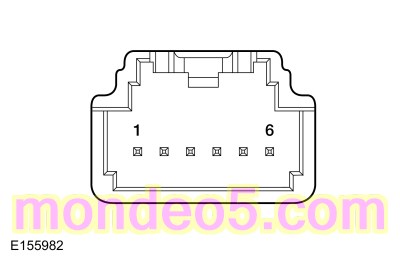 C233-2 (component side)
|
|
C233-5 (component side)
|
-
Compare the resistance values to the table below:
|
Ambient Temperature
|
Approximate Resistance
|
|
-40°C (-40°F)
|
901,490 ohms
|
|
-15°C (5°F)
|
208,450 ohms
|
|
0°C (32°F)
|
95,560 ohms
|
|
15°C (59°F)
|
46,750 ohms
|
|
25°C (77°F)
|
30,000 ohms
|
|
35°C (95°F)
|
19,720 ohms
|
|
60°C (140°F)
|
7,592 ohms
|
|
85°C (185°F)
|
3,286 ohms
|
Did the in-vehicle temperature and humidity sensor test OK?
|
| N3
CHECK THE IN-VEHICLE TEMPERATURE AND HUMIDITY SENSOR FAN MOTOR CIRCUITS
|
-
Press the
button (indicator ON).
-
Measure:
|
Positive Lead
|
Measurement / Action
|
Negative Lead
|
|
C233-6
|
|
C233-1
|
Is the voltage greater than 11 volts?
| Yes
|
INSTALL a new in-vehicle temperature and humidity sensor.
REFER to:
In-Vehicle Temperature and Humidity Sensor
(412-00 Climate Control System - General Information, Removal and Installation).
CLEAR the DTCs. REPEAT the self-test. If the DTC returns, GO to
N9
|
| No
|
VERIFY the
fuse 21 (5A) is OK. If not OK, REFER to the Wiring Diagrams manual to identify the possible causes of the circuit short.
If OK, GO to
N4
|
|
| N4
CHECK THE IN-VEHICLE TEMPERATURE AND HUMIDITY SENSOR CIRCUITS FOR A SHORT TO VOLTAGE
|
-
Disconnect In-vehicle temperature and humidity sensor C233
.
-
Disconnect
fuse 21 (5A) .
-
Measure:
|
Positive Lead
|
Measurement / Action
|
Negative Lead
|
|
C233-1
|
|
Ground
|
|
C233-2
|
|
Ground
|
|
C233-3
|
|
Ground
|
|
C233-4
|
|
Ground
|
|
C233-5
|
|
Ground
|
|
C233-6
|
|
Ground
|
Is any voltage present?
|
| N5
CHECK THE IN-VEHICLE TEMPERATURE AND HUMIDITY SENSOR CIRCUITS FOR A SHORT TO GROUND
|
-
Measure:
|
Positive Lead
|
Measurement / Action
|
Negative Lead
|
|
C233-1
|
|
Ground
|
|
C233-2
|
|
Ground
|
|
C233-3
|
|
Ground
|
|
C233-4
|
|
Ground
|
|
C233-5
|
|
Ground
|
|
C233-6
|
|
Ground
|
Are the resistances greater than 10,000 ohms?
|
| N6
CHECK THE IN-VEHICLE TEMPERATURE AND HUMIDITY SENSOR CIRCUITS FOR AN OPEN
|
-
Measure:
|
Positive Lead
|
Measurement / Action
|
Negative Lead
|
|
C233-3
|
|
C2402A-3
|
|
C233-5
|
|
C2402A-2
|
|
Positive Lead
|
Measurement / Action
|
Negative Lead
|
|
C233-1
|
|
C2402B-27
|
|
C233-2
|
|
C2402B-29
|
|
C233-4
|
|
C2402B-19
|
|
Positive Lead
|
Measurement / Action
|
Negative Lead
|
|
C233-6
|
|
fuse 21 cavity, (component side)
|
Are the resistances less than 3 ohms?
|
| N7
CHECK THE IN-VEHICLE TEMPERATURE AND HUMIDITY SENSOR CIRCUITS FOR A SHORT TOGETHER
|
-
Measure:
|
Positive Lead
|
Measurement / Action
|
Negative Lead
|
|
C233-1
|
|
C233-2
|
|
C233-1
|
|
C233-3
|
|
C233-1
|
|
C233-4
|
|
C233-1
|
|
C233-5
|
|
C233-1
|
|
C233-6
|
|
C233-2
|
|
C233-3
|
|
C233-2
|
|
C233-4
|
|
C233-2
|
|
C233-5
|
|
C233-2
|
|
C233-6
|
|
C233-3
|
|
C233-4
|
|
C233-3
|
|
C233-5
|
|
C233-3
|
|
C233-6
|
|
C233-4
|
|
C233-5
|
|
C233-4
|
|
C233-6
|
|
C233-5
|
|
C233-6
|
Are the resistances greater than 10,000 ohms?
|
| N8
CHECK FOR CORRECT IN-VEHICLE TEMPERATURE AND HUMIDITY SENSOR OPERATION
|
-
Inspect the disconnected connectors.
-
Repair:
-
corrosion (install new connector or terminals – clean module pins)
-
damaged or bent pins – install new terminals/pins
-
pushed-out pins – install new pins as necessary
-
Connect all disconnected connectors. Make sure they seat and latch correctly.
-
Operate the system and determine if the concern is still present.
Is the concern still present?
| Yes
|
INSTALL a new in-vehicle temperature sensor.
REFER to:
In-Vehicle Temperature and Humidity Sensor
(412-00 Climate Control System - General Information, Removal and Installation).
TEST the system for normal operation. If the concern is still present, GO to
N9
|
| No
|
The system is operating correctly at this time. The concern may have been caused by a loose or corroded connector. ADDRESS
the root cause of any connector or pin issues.
|
|
| N9
CHECK FOR CORRECT FCIM (FRONT CONTROLS INTERFACE MODULE)
OPERATION
|
-
Disconnect and inspect all the
connectors.
-
Repair:
-
corrosion (install new connector or terminals – clean module pins)
-
damaged or bent pins – install new terminals/pins
-
pushed-out pins – install new pins as necessary
-
Connect the
connectors. Make sure they seat and latch correctly.
-
Operate the system and determine if the concern is still present.
Is the concern still present?
| Yes
|
CHECK
for any applicable Technical Service Bulletins (TSBs). If a
exists for this concern, DISCONTINUE this test and FOLLOW
instructions. If no Technical Service Bulletins (TSBs) address this concern, INSTALL a new
.
For vehicles equipped with Sony® Audio System,
REFER to:
Front Controls Interface Module (FCIM)
(415-00C Information and Entertainment System - General Information - Vehicles With: AM/FM/CD/SYNC/Sony Audio System, Removal and Installation).
For vehicles equipped with Touchscreen Display,
REFER to:
Front Controls Interface Module (FCIM)
(415-00B Information and Entertainment System - General Information - Vehicles With: AM/FM/CD/SYNC/Touchscreen Display, Removal and Installation).
For all other audio systems,
REFER to:
Front Controls Interface Module (FCIM)
(415-00A Information and Entertainment System - General Information - Vehicles With: AM/FM/CD/SYNC, Removal and Installation).
|
| No
|
The system is operating correctly at this time. The concern may have been caused by a loose or corroded connector. ADDRESS
the root cause of any connector or pin issues.
|
|
B1A63:11, B1A63:15, B1A64:11, B1A64:15
Refer to Wiring Diagrams Cell 55 for schematic and connector information.
Normal Operation and Fault Conditions
Sunload Sensor,
REFER to:
Climate Control System - Vehicles With: Dual Automatic Temperature Control (DATC) - System Operation and Component Description
(412-00 Climate Control System - General Information, Description and Operation).
DTC Fault Trigger Conditions
|
DTC
|
Description
|
Fault Trigger Conditions
|
|
B1A63:11
|
Right Solar Sensor: Circuit Short To Ground
|
This
sets when the control module senses lower than expected voltage on the
sensor feedback circuit, indicating a short to ground.
|
|
B1A63:15
|
Right Solar Sensor: Circuit Short To Battery or Open
|
This
sets when the control module senses higher than expected voltage on the
sensor feedback circuit, indicating a short to voltage or an open circuit or sensor.
|
|
B1A64:11
|
Left Solar Sensor: Circuit Short To Ground
|
This
sets when the control module senses lower than expected voltage on the
sensor feedback circuit, indicating a short to ground.
|
|
B1A64:15
|
Left Solar Sensor: Circuit Short To Battery or Open
|
This
sets when the control module senses higher than expected voltage on the
sensor feedback circuit, indicating a short to voltage or an open circuit or sensor.
|
Possible Sources
-
Wiring, terminals or connectors
-
Sunload sensor
-
-
Inspect loose or corroded
and sunload sensor connections.
PINPOINT TEST O : B1A63:11, B1A63:15, B1A64:11, B1A64:15
| NOTICE:
Use the correct probe adapter(s) when making measurements. Failure to use the correct probe adapter(s) may damage the connector.
|
| O1
CHECK THE SUNLOAD SENSOR FOR VOLTAGE
|
-
Disconnect Sunload Sensor C286
.
-
Measure:
|
Positive Lead
|
Measurement / Action
|
Negative Lead
|
|
C286-2
|
|
C286-4
|
Is the voltage between 4.7 and 5.1 volts?
|
| O2
CHECK THE SUNLOAD SENSOR VOLTAGE CIRCUIT
|
-
Measure:
|
Positive Lead
|
Measurement / Action
|
Negative Lead
|
|
C286-2
|
|
Ground
|
Is the voltage between 4.7 and 5.1 volts?
| Yes
|
REPAIR ground circuit RLF14 (GY/BN).
|
|
| O3
CHECK THE SUNLOAD SENSOR SIGNAL CIRCUITS FOR A SHORT TO VOLTAGE
|
-
Measure:
|
Positive Lead
|
Measurement / Action
|
Negative Lead
|
|
C286-1
|
|
Ground
|
|
C286-3
|
|
Ground
|
Is any voltage present?
|
| O4
CHECK THE SUNLOAD SENSOR SIGNAL CIRCUITS FOR A SHORT TO GROUND
|
-
Measure:
|
Positive Lead
|
Measurement / Action
|
Negative Lead
|
|
C286-1
|
|
Ground
|
|
C286-3
|
|
Ground
|
Is the resistance greater than 10,000 ohms?
|
| O5
CHECK THE SUNLOAD SENSOR SIGNAL CIRCUITS FOR AN OPEN
|
-
Measure:
|
Positive Lead
|
Measurement / Action
|
Negative Lead
|
|
C286-1
|
|
C2402B-22
|
|
C286-3
|
|
C2402B-21
|
Is the resistance less than 3 ohms?
|
| O6
CHECK THE SUNLOAD SENSOR SIGNAL CIRCUITS FOR A SHORT TO EACH OTHER
|
-
Measure:
|
Positive Lead
|
Measurement / Action
|
Negative Lead
|
|
C286-1
|
|
C286-3
|
Is the resistance greater than 10,000 ohms?
| Yes
|
INSTALL a new sunload sensor.
REFER to:
Sunload Sensor
(412-00 Climate Control System - General Information, Removal and Installation).
TEST the system for normal operation. If the concern is still present, GO to
O7
|
|
| O7
CHECK FOR CORRECT FCIM (FRONT CONTROLS INTERFACE MODULE)
OPERATION
|
-
Disconnect and inspect all the
connectors.
-
Repair:
-
corrosion (install new connector or terminals – clean module pins)
-
damaged or bent pins – install new terminals/pins
-
pushed-out pins – install new pins as necessary
-
Connect the
connectors. Make sure they seat and latch correctly.
-
Operate the system and determine if the concern is still present.
Is the concern still present?
| Yes
|
CHECK
for any applicable Technical Service Bulletins (TSBs). If a
exists for this concern, DISCONTINUE this test and FOLLOW
instructions. If no Technical Service Bulletins (TSBs) address this concern, INSTALL a new
.
For vehicles equipped with Sony® Audio System,
REFER to:
Front Controls Interface Module (FCIM)
(415-00C Information and Entertainment System - General Information - Vehicles With: AM/FM/CD/SYNC/Sony Audio System, Removal and Installation).
For vehicles equipped with Touchscreen Display,
REFER to:
Front Controls Interface Module (FCIM)
(415-00B Information and Entertainment System - General Information - Vehicles With: AM/FM/CD/SYNC/Touchscreen Display, Removal and Installation).
For all other audio systems,
REFER to:
Front Controls Interface Module (FCIM)
(415-00A Information and Entertainment System - General Information - Vehicles With: AM/FM/CD/SYNC, Removal and Installation).
|
| No
|
The system is operating correctly at this time. The concern may have been caused by a loose or corroded connector. ADDRESS
the root cause of any connector or pin issues.
|
|
B1B71:11, B1B71:15
Refer to Wiring Diagrams Cell 55 for schematic and connector information.
Normal Operation and Fault Conditions
Evaporator Temperature Sensor,
REFER to:
Climate Control System - Vehicles With: Dual Automatic Temperature Control (DATC) - System Operation and Component Description
(412-00 Climate Control System - General Information, Description and Operation).
DTC Fault Trigger Conditions
|
DTC
|
Description
|
Fault Trigger Conditions
|
|
B1B71:11
|
Evaporator Temperature Sensor: Circuit Short To Ground
|
The module senses excessive voltage drop on the sensor reference voltage circuit, indicating a short directly to ground. The
module disables automatic-recirculation and the compressor is shut off.
|
|
B1B71:15
|
Evaporator Temperature Sensor: Circuit Short To Battery or Open
|
The module senses no voltage drop on the sensor reference voltage circuit, indicating a short directly to voltage or an open
circuit. The module disables automatic-recirculation and the compressor is shut off.
|
Possible Sources
-
Wiring, terminals or connectors
-
Evaporator temperature sensor
-
control module
PINPOINT TEST P : B1B71:11, B1B71:15
| NOTICE:
Use the correct probe adapter(s) when making measurements. Failure to use the correct probe adapter(s) may damage the connector.
|
| P1
CHECK THE EVAPORATOR TEMPERATURE SENSOR RESISTANCE
|
-
Disconnect Evaporator Temperature Sensor C296
.
-
Measure:
|
Positive Lead
|
Measurement / Action
|
Negative Lead
|
|
C296-1 (component side)
|
|
C296-2 (component side)
|
-
Compare the evaporator temperature sensor measured resistance with the table below.
|
Ambient Temperature
°F (
°C)
|
Resistance
|
|
23.0
°F (
-5
°C)
|
111,677-136,089 ohms
|
|
32.0
°F (
°C)
|
87,028-106,252 ohms
|
|
41.0
°F (
5
°C)
|
67,969-82,801 ohms
|
|
50.0
°F (
10
°C)
|
53,505-64,741 ohms
|
|
59.0
°F (
15
°C)
|
42,389-51,206 ohms
|
|
68.0
°F (
20
°C)
|
33,860-40,844 ohms
|
|
77.0
°F (
25
°C)
|
27,058-32,942 ohms
|
|
86.0
°F (
30
°C)
|
21,443-27,036 ohms
|
|
95.0
°F (
35
°C)
|
16,583-22,808 ohms
|
|
103.9
°F (
40
°C)
|
12,177-20,007 ohms
|
Is the resistance within the specified values for the temperatures?
| No
|
INSTALL a new evaporator temperature sensor.
REFER to:
Evaporator Temperature Sensor
(412-00 Climate Control System - General Information, Removal and Installation).
|
|
| P2
CHECK THE EVAPORATOR TEMPERATURE SENSOR INPUT CIRCUIT FOR A SHORT TO VOLTAGE
|
-
Measure:
|
Positive Lead
|
Measurement / Action
|
Negative Lead
|
|
C2402A-19
|
|
Ground
|
Is any voltage present?
|
| P3
CHECK THE EVAPORATOR TEMPERATURE SENSOR INPUT CIRCUIT FOR A SHORT TO GROUND
|
-
Measure:
|
Positive Lead
|
Measurement / Action
|
Negative Lead
|
|
C2402A-19
|
|
Ground
|
Is the resistance greater than 10,000 ohms?
|
| P4
CHECK THE EVAPORATOR TEMPERATURE SENSOR INPUT CIRCUIT FOR AN OPEN
|
-
Measure:
|
Positive Lead
|
Measurement / Action
|
Negative Lead
|
|
C2402A-19
|
|
C296-2
|
Is the resistance less than 3 ohms?
|
| P5
CHECK THE EVAPORATOR TEMPERATURE SENSOR SIGNAL AND SIGNAL RETURN CIRCUITS FOR A SHORT TOGETHER
|
-
Measure:
|
Positive Lead
|
Measurement / Action
|
Negative Lead
|
|
C2402A-19
|
|
C2402A-2
|
Is the resistance greater than 10,000 ohms?
|
| P6
CHECK FOR CORRECT FCIM (FRONT CONTROLS INTERFACE MODULE)
OPERATION
|
-
Disconnect and inspect all the
connectors.
-
Repair:
-
corrosion (install new connector or terminals – clean module pins)
-
damaged or bent pins – install new terminals/pins
-
pushed-out pins – install new pins as necessary
-
Connect the
connectors. Make sure they seat and latch correctly.
-
Operate the system and determine if the concern is still present.
Is the concern still present?
| Yes
|
CHECK
for any applicable Technical Service Bulletins (TSBs). If a
exists for this concern, DISCONTINUE this test and FOLLOW
instructions. If no Technical Service Bulletins (TSBs) address this concern, INSTALL a new
.
For vehicles equipped with Sony® Audio System,
REFER to:
Front Controls Interface Module (FCIM)
(415-00C Information and Entertainment System - General Information - Vehicles With: AM/FM/CD/SYNC/Sony Audio System, Removal and Installation).
For vehicles equipped with Touchscreen Display,
REFER to:
Front Controls Interface Module (FCIM)
(415-00B Information and Entertainment System - General Information - Vehicles With: AM/FM/CD/SYNC/Touchscreen Display, Removal and Installation).
For all other audio systems,
REFER to:
Front Controls Interface Module (FCIM)
(415-00A Information and Entertainment System - General Information - Vehicles With: AM/FM/CD/SYNC, Removal and Installation).
|
| No
|
The system is operating correctly at this time. The concern may have been caused by a loose or corroded connector. ADDRESS
the root cause of any connector or pin issues.
|
|
C1B14:11, C1B14:12
Refer to Wiring Diagrams Cell 55 for schematic and connector information.
Normal Operation and Fault Conditions
A 5-volt reference voltage and ground is supplied to the climate control sensors and actuators from the
.
DTC Fault Trigger Conditions
|
DTC
|
Description
|
Fault Trigger Conditions
|
|
C1B14:11
|
Air Distribution Damper Motor: Circuit Short to Ground
|
This
sets when the module senses less than 5 volts on the sensor reference voltage circuit, indicating a short to ground.
|
|
C1B14:12
|
Air Distribution Damper Motor: Circuit Short to Battery
|
This
sets when the module senses greater than 5 volts on the sensor reference voltage circuit, indicating a short to voltage.
|
Possible Sources
-
Wiring, terminals or connectors
-
PINPOINT TEST Q : C1B14:11, C1B14:12
| NOTICE:
Use the correct probe adapter(s) when making measurements. Failure to use the correct probe adapter(s) may damage the connector.
|
| Q1
CHECK THE FCIM (FRONT CONTROLS INTERFACE MODULE)
DTCS
|
-
Using a diagnostic scan tool, perform
self-test.
Is DTC C1B14:11 present?
|
| Q2
CHECK THE REFERENCE VOLTAGE CIRCUIT FOR A SHORT TO GROUND
|
-
Measure:
|
Positive Lead
|
Measurement / Action
|
Negative Lead
|
|
C2402A-3
|
|
Ground
|
Is the resistance greater than 10,000 ohms?
|
| Q3
CHECK THE REFERENCE VOLTAGE CIRCUIT AND THE SIGNAL RETURN CIRCUIT FOR A SHORT TOGETHER
|
-
Measure:
|
Positive Lead
|
Measurement / Action
|
Negative Lead
|
|
C2402A-3
|
|
C2402A-2
|
Is the resistance greater than 200 ohms?
|
| Q4
CHECK THE A/C (AIR CONDITIONING)
COMPONENTS
|
-
Measure:
|
Positive Lead
|
Measurement / Action
|
Negative Lead
|
|
C2402A-3
|
|
C2402A-2
|
-
While measuring the resistance, disconnect the following components one at a time, in order. Stop disconnecting components
if the measured resistance rises above 200 ohms.
-
In-vehicle temperature and humidity sensor C233
-
Evaporator temperature sensor C296
-
Driver side register air discharge temperature sensor C2438
-
Driver side footwell air discharge temperature sensor C2436
-
Passenger side register air discharge temperature sensor C2439
-
Passenger side footwell air discharge temperature sensor C2437
-
Air distribution door actuator C236
-
Passenger temperature door actuator C2092
-
Air inlet door actuator C289
Did the resistance rise above 200 ohms?
| Yes
|
INSTALL a new sensor or actuator (the last one to be disconnected). Refer to the appropriate section in Group 412 for the procedure. When installing an actuator, CONNECT the actuator electrical connector before the
. This allows the actuator to be calibrated when the
is connected.
|
|
| Q5
CHECK THE REFERENCE VOLTAGE CIRCUIT FOR A SHORT TO VOLTAGE
|
-
Measure:
|
Positive Lead
|
Measurement / Action
|
Negative Lead
|
|
C2402A-3
|
|
Ground
|
Is any voltage present?
|
| Q6
CHECK FOR CORRECT FCIM (FRONT CONTROLS INTERFACE MODULE)
OPERATION
|
-
Disconnect and inspect all the
connectors.
-
Repair:
-
corrosion (install new connector or terminals – clean module pins)
-
damaged or bent pins – install new terminals/pins
-
pushed-out pins – install new pins as necessary
-
Connect the
connectors. Make sure they seat and latch correctly.
-
Operate the system and determine if the concern is still present.
Is the concern still present?
| Yes
|
CHECK
for any applicable Technical Service Bulletins (TSBs). If a
exists for this concern, DISCONTINUE this test and FOLLOW
instructions. If no Technical Service Bulletins (TSBs) address this concern, INSTALL a new
.
For vehicles equipped with Sony® Audio System,
REFER to:
Front Controls Interface Module (FCIM)
(415-00C Information and Entertainment System - General Information - Vehicles With: AM/FM/CD/SYNC/Sony Audio System, Removal and Installation).
For vehicles equipped with Touchscreen Display,
REFER to:
Front Controls Interface Module (FCIM)
(415-00B Information and Entertainment System - General Information - Vehicles With: AM/FM/CD/SYNC/Touchscreen Display, Removal and Installation).
For all other audio systems,
REFER to:
Front Controls Interface Module (FCIM)
(415-00A Information and Entertainment System - General Information - Vehicles With: AM/FM/CD/SYNC, Removal and Installation).
|
| No
|
The system is operating correctly at this time. The concern may have been caused by a loose or corroded connector. ADDRESS
the root cause of any connector or pin issues.
|
|
Insufficient Heat In Auto Start-Stop Mode Only
Refer to Wiring Diagrams Cell 40 for schematic and connector information.
Normal Operation and Fault Conditions
Cabin Heater Coolant Pump - vehicles equipped with Auto Start-Stop,
REFER to:
Climate Control System - Vehicles With: Dual Automatic Temperature Control (DATC) - System Operation and Component Description
(412-00 Climate Control System - General Information, Description and Operation).
DTC Fault Trigger Conditions
|
DTC
|
Description
|
Fault Trigger Conditions
|
|
P2601
|
Coolant Pump "A" Control Circuit Performance/Stuck Off
|
-
This
sets when the
senses any of the following conditions:
-
Dry-Run leads to cabin heater coolant pump running without resistance
-
Over Temperature
-
Over/Under Voltage
-
Impeller Stall
-
Impeller Speed below minimum speed
-
Internal Error
|
|
P2602
|
Coolant Pump "A" Control Circuit Low
|
This
sets when the
senses low voltage on the
circuit when commanding it high, indicating a short to ground to the cabin heater coolant pump.
|
|
P2603
|
Coolant Pump "A" Control Circuit High
|
This
sets when the
senses low voltage on the
circuit when commanding it high, indicating an open circuit to the cabin heater coolant pump.
|
Possible Causes
-
Wiring, terminals or connectors
-
Low coolant or air in the coolant system
-
Cabin heater coolant pump
-
PINPOINT TEST R : INSUFFICIENT HEAT IN AUTO START-STOP MODE ONLY
| R1
CHECK THE CABIN HEATER COOLANT PUMP
|
|
NOTE:
The engine must be auto-stopped to request the cabin heater coolant pump on. Further information can be found in the Owner's
Literature for full Auto Start-Stop enabling/disabling.
-
Start the vehicle and allow engine to reach normal operating temperatures.
-
Using the
controls, select panel mode, set temperature to full hot and set blower speed to low.
-
Drive the vehicle above 3 mph (4 km/h).
-
Stop the vehicle on a level surface.
-
Make sure that the steering wheel is set to the straight ahead position.
-
Keep the transmission selector lever in position D, brake pedal pressed and doors closed.
-
Using a diagnostic scan tool, view
Parameter Identifications (PIDs).
-
Monitor the
coolant pump status (COOLPMP_A_STAT)
for at least 1 minute.
Does the cabin heater coolant pump turn on?
|
| R2
CHECK THE CABIN HEATER COOLANT PUMP CIRCUITS FOR A SHORT TO VOLTAGE
|
-
Disconnect
fuse 12 (15A) .
-
Disconnect
1.5L C1915B or 1.6L C1232B
.
-
Disconnect Cabin heater coolant pump C163
.
-
Measure:
|
Positive Lead
|
Measurement / Action
|
Negative Lead
|
|
C163-1
|
|
Ground
|
|
C163-2
|
|
Ground
|
|
C163-3
|
|
Ground
|
Is there any voltage present?
|
| R3
CHECK THE CABIN HEATER COOLANT PUMP CIRCUITS FOR A SHORT TO GROUND
|
-
Measure:
|
Positive Lead
|
Measurement / Action
|
Negative Lead
|
|
C163-2
|
|
Ground
|
|
C163-3
|
|
Ground
|
Are the resistances greater than 10,000 ohms?
|
| R4
CHECK THE CABIN HEATER COOLANT PUMP CIRCUITS FOR AN OPEN
|
Are the resistances less than 3 ohms?
|
| R5
CHECK THE CABIN HEATER COOLANT PUMP CIRCUITS FOR A SHORT TOGETHER
|
-
Measure:
|
Positive Lead
|
Measurement / Action
|
Negative Lead
|
|
C163-1
|
|
C163-2
|
|
C163-1
|
|
C163-3
|
|
C163-2
|
|
C163-3
|
Is the resistance greater than 10,000 ohms?
|
| R6
CHECK THE ENGINE COOLANT LEVEL
|
|
NOTE:
Allow the engine to cool before checking the engine coolant level.
-
Visually inspect the engine coolant level at the degas bottle.
Is the engine coolant level within specifications?
| No
|
For 1.5L engine,
REFER to:
Engine Cooling
(303-03A Engine Cooling - 1.5L EcoBoost (118kW/160PS), Diagnosis and Testing).
For 1.6L engine,
REFER to:
Engine Cooling
(303-03B Engine Cooling - 1.6L EcoBoost (132kW/180PS) - Sigma, Diagnosis and Testing).
|
|
| R7
CLEAR ALL PCM (POWERTRAIN CONTROL MODULE)
DIAGNOSTIC TROUBLE CODES
|
-
Connect all disconnected connectors. Make sure they seat and latch correctly.
-
Using a diagnostic scan tool, CLEAR all
Diagnostic Trouble Codes (DTCs).
-
NOTE:
The engine must be auto-stopped to request the cabin heater coolant pump on. Further information can be found in the Owner's
Literature for full Auto Start-Stop enabling/disabling.
Start the vehicle and allow engine to reach normal operating temperatures.
-
Using the
controls, select panel mode, set temperature to full hot and set blower speed to low.
-
Drive the vehicle above 3 mph (4 km/h).
-
Stop the vehicle on a level surface.
-
Make sure that the steering wheel is set to the straight ahead position.
-
Keep the transmission selector lever in position D, brake pedal pressed and doors closed.
-
Using a diagnostic scan tool, view
Parameter Identifications (PIDs).
-
Monitor the
coolant pump status (COOLPMP_A_STAT)
for at least 1 minute.
Does the cabin coolant pump turn on?
| Yes
|
If the cabin coolant pump runs for 10 seconds on and 10 seconds off, PURGE the air from the coolant system.
REFER to:
Cooling System Draining and Vacuum Filling
(303-03A Engine Cooling - 1.5L EcoBoost (118kW/160PS), General Procedures).
REFER to:
Cooling System Draining and Vacuum Filling
(303-03B Engine Cooling - 1.6L EcoBoost (132kW/180PS) - Sigma, General Procedures).
If the cabin coolant pump runs normally, the system is operating correctly at this time. The concern may have been caused
by pump connections. ADDRESS the root cause of any connector or pin issues.
|
|
| R8
CHECK FOR CORRECT PCM (POWERTRAIN CONTROL MODULE)
OPERATION
|
-
Disconnect and inspect the
connectors.
-
Repair:
-
corrosion (replace connector or terminals – clean module pins)
-
damaged or bent pins – replace terminals/pins
-
pushed-out pins – replace pins as necessary
-
Connect the
connectors. Make sure they seat and latch correctly.
-
Operate the system and verify the concern is still present.
Is the concern still present?
| Yes
|
CHECK
for any applicable Technical Service Bulletins (TSBs). If a
exists for this concern, DISCONTINUE this test and FOLLOW
instructions. If no Technical Service Bulletins (TSBs) address this concern, INSTALL a new
.
For 1.5L,
REFER to:
Powertrain Control Module (PCM)
(303-14A Electronic Engine Controls - 1.5L EcoBoost (118kW/160PS), Removal and Installation).
For 1.6L,
REFER to:
Powertrain Control Module (PCM)
(303-14B Electronic Engine Controls - 1.6L EcoBoost (132kW/180PS) - Sigma, Removal and Installation).
|
| No
|
The system is operating correctly at this time. The concern may have been caused by module connections. ADDRESS the root cause
of any connector or pin issues.
|
|
P06A0
Refer to Wiring Diagrams Cell 55 for schematic and connector information.
Normal Operation and Fault Conditions
The externally controlled variable displacement compressor is electronically controlled by the
. The
pulse width modulates the ground to the externally controlled variable displacement compressor to change the displacement
of the
compressor.
DTC Fault Trigger Conditions
|
DTC
|
Description
|
Fault Trigger Conditions
|
|
P06A0
|
Variable A/C Compressor Control Circuit
|
The
senses greater than expected voltage on the sensor feedback circuit, indicating a short to voltage or an open circuit or
sensor.
|
Possible Sources
-
Wiring, terminals or connectors
-
compressor
-
Visual Inspection and Diagnostic Pre-checks
-
Inspect for loose or corroded
and
compressor connections.
PINPOINT TEST S : P06A0
| S1
CHECK FOR VOLTAGE TO THE A/C (AIR CONDITIONING)
COMPRESSOR CONTROL SOLENOID
|
-
Disconnect
Compressor Control Solenoid C1110
.
-
Measure:
|
Positive Lead
|
Measurement / Action
|
Negative Lead
|
|
C1110-2
|
|
Ground
|
Is the voltage greater than 11 volts?
| No
|
VERIFY the
fuse 12 (15A) is OK. If OK, REPAIR the circuit. If not OK, REFER to the Wiring Diagrams manual to identify the possible causes
of the circuit short.
|
|
| S2
CHECK THE A/C (AIR CONDITIONING)
COMPRESSOR DISPLACEMENT CONTROL SOLENOID PWM (PULSE WIDTH MODULATION)
CIRCUIT FOR A SHORT TO GROUND
|
-
Disconnect
1.5L C1915B, 1.6L C1232B, 2.0L C1381B or 2.5L C1551B
.
-
Measure:
|
Positive Lead
|
Measurement / Action
|
Negative Lead
|
|
C1110-1
|
|
Ground
|
Is the resistance greater than 10,000 ohms?
|
| S3
CHECK THE A/C (AIR CONDITIONING)
COMPRESSOR DISPLACEMENT CONTROL SOLENOID PWM (PULSE WIDTH MODULATION)
CIRCUIT FOR A SHORT TO VOLTAGE
|
-
Measure:
|
Positive Lead
|
Measurement / Action
|
Negative Lead
|
|
C1110-1
|
|
Ground
|
Is any voltage present?
|
| S4
CHECK THE A/C (AIR CONDITIONING)
COMPRESSOR DISPLACEMENT CONTROL SOLENOID PWM (PULSE WIDTH MODULATION)
CIRCUIT FOR AN OPEN
|
-
Measure:
1.5L
|
Positive Lead
|
Measurement / Action
|
Negative Lead
|
|
C1110-1
|
|
C1915B-41
|
1.6L
|
Positive Lead
|
Measurement / Action
|
Negative Lead
|
|
C1110-1
|
|
C1232B-41
|
2.0L
|
Positive Lead
|
Measurement / Action
|
Negative Lead
|
|
C1110-1
|
|
C1381B-41
|
2.5L
|
Positive Lead
|
Measurement / Action
|
Negative Lead
|
|
C1110-1
|
|
C1551B-1
|
Is the resistance less than 3 ohms?
|
| S5
CHECK FOR CORRECT PCM (POWERTRAIN CONTROL MODULE)
OPERATION
|
-
Disconnect and inspect all
connectors.
-
Repair:
-
corrosion (install new connector or terminals – clean module pins)
-
damaged or bent pins – install new terminals/pins
-
pushed-out pins – install new pins as necessary
-
Connect the
connectors. Make sure they seat and latch correctly.
-
Operate the system and determine if the concern is still present.
Is the concern still present?
| Yes
|
CHECK
for any applicable Technical Service Bulletins (TSBs). If a
exists for this concern, DISCONTINUE this test and FOLLOW
instructions. If no Technical Service Bulletins (TSBs) address this concern, INSTALL a new
.
For 1.5L,
REFER to:
Powertrain Control Module (PCM)
(303-14A Electronic Engine Controls - 1.5L EcoBoost (118kW/160PS), Removal and Installation).
For 1.6L,
REFER to:
Powertrain Control Module (PCM)
(303-14B Electronic Engine Controls - 1.6L EcoBoost (132kW/180PS) - Sigma, Removal and Installation).
For 2.0L,
REFER to:
Powertrain Control Module (PCM)
(303-14C Electronic Engine Controls - 2.0L EcoBoost (184kW/250PS) - MI4, Removal and Installation).
For 2.5L,
REFER to:
Powertrain Control Module (PCM)
(303-14D Electronic Engine Controls - 2.5L Duratec (125kW/170PS), Removal and Installation).
|
| No
|
The system is operating correctly at this time. The concern may have been caused by a loose or corroded connector. ADDRESS
the root cause of any connector or pin issues.
|
|
Refrigerant System Tests Diagnostic Table
-
NOTE:
The following table is used to guide diagnosis of the refrigerant system if operating pressures are outside normal limits.
NOTE:
Variable compressors operate at lower pressures and are dependent on correct system charge for normal operation.
Refer to the chart below.
|
High (Discharge) Pressure
|
Low (Suction) Pressure
|
Component — Causes
|
|
High
|
Normal to High
|
-
Condenser — inadequate airflow.
-
Engine — overheating.
|
|
Normal to High
|
Normal
|
-
Refrigerant overcharge — air in refrigerant.
|
|
Normal to Low
|
High
|
-
Compressor — low performance.
-
Before condemning the
compressor verify the refrigerant system has the correct system charge.
|
|
Normal to Low
|
Normal to High
|
-
suction line — partially restricted or plugged.
a
|
|
Normal to Low
|
Low
|
-
Low refrigerant charge — leak in system.
-
suction line — partially restricted or plugged.
b
|
|
Erratic Operation or Compressor Not Running
|
-
Ambient Air Temperature (AAT) sensor — poor connection.
-
pressure transducer — poor connection.
-
Evaporator temperature sensor — poor connection.
-
Low refrigerant charge — leak in system.
|
|
Additional Possible Components or Causes Associated With Inadequate Compressor Operation
|
-
Compressor Drive Belt — loose
-
Compressor Clutch — slipping
-
Clutch Coil Open — shorted, or loose mounting
-
Control Assembly Switch — dirty contacts or sticking open
-
Clutch Wiring Circuit — high resistance, open or blown fuse
-
Compressor Operation Interrupted by Engine Computer
|
|
Additional Possible Components or Causes Associated With a Damaged Compressor
|
-
Incorrect Clutch Air-gap
-
Suction Accumulator — refrigerant oil bleed hose plugged
-
Refrigerant Leaks
|
Component Test- Heater Core
NOTE:
If a heater core leak is suspected, test the heater core by following the plugged heater core component test before the heater
core pressure test. Carry out a system inspection by checking the heater system thoroughly as follows:
-
Inspect for evidence of coolant leakage at the heater hose to heater core attachments. A coolant leak in the heater hose could
follow the heater core tube to the heater core and appear as a leak in the heater core.
NOTE:
Spring-type clamps are installed as original equipment. Installation and overtightening of non-specified clamps can cause
leakage at the heater hose connection and damage the heater core.
-
Check the integrity of the heater hose clamps.
Heater Core - Plugged
-
Check to see the engine coolant is at the correct level.
-
Start the engine and turn on the heater.
-
When the engine coolant reaches operating temperature, check the heater core inlet and outlet hoses to see if they are hot.
-
If the outlet only is not hot:
-
the heater core may have an air pocket.
-
the heater core may be plugged.
-
If the inlet only is not hot, the thermostat may not be working correctly.
Heater Core - Pressure Test
NOTE:
Due to space limitations, a bench test may be necessary for pressure testing.
-
Drain the coolant from the cooling system.
-
Disconnect the heater hoses from the heater core.
-
Install a short piece of heater hose, approximately 101 mm (4 in) long on each heater core tube.
-
Fill the heater core and heater hoses with water and install the plug BT-7422-B and the adapter BT-7422-A from the Pressure
Test Kit. Secure the heater hoses, plug and adapter with hose clamps.
-
Attach the pump and gauge assembly from the Pressure Test Kit to the adapter.
-
Close the bleed valve at the base of the gauge. Pump 138 kPa (20 psi) of air pressure into the heater core.
-
Observe the pressure gauge for a minimum of 3 minutes.
-
If the pressure drops, check the heater hose connections to the core tubes for leaks. If the heater hoses do not leak, remove
the heater core from the vehicle and carry out the bench test.
Heater Core - Bench Test
-
Remove the heater core from the vehicle.
-
Drain all of the coolant from the heater core.
-
Connect the 101 mm (4 in) test heater hoses with plug and adapter to the core tubes. Then connect the Pressure Test Kit to
the adapter.
-
Apply 138 kPa (20 psi) of air pressure to the heater core. Submerge the heater core in water.
-
If a leak is observed, install a new heater core.
Component Test- Evaporator or Condenser Core On-Vehicle Leak Test
-
Discharge and recover the refrigerant.
-
Disconnect the suspect evaporator core or condenser core from the
system.
-
Clean the manifold fittings.
-
Connect the appropriate test fittings from the
Flush Adapter Kit to the condenser or evaporator core tube connections.
NOTE:
The automatic shut-off valves on some gauge set hoses do not open when connected to the test fittings. If available, use hoses
without shut-off valves. If hoses with shut-off valves are used, make sure the valve opens when attached to the test fittings
or install an adapter that will activate the valve. The test is not valid if the shut-off valve does not open.
-
Connect the red and blue hoses from the R-134a Manifold Gauge Set to the test fittings on the evaporator core or condenser
core. Connect the yellow hose to a known good vacuum pump.
-
Open both gauge set valves and start the vacuum pump. Allow the vacuum pump to operate for a minimum of 45 minutes after the
gauge set low pressure gauge indicates 101 kPa (30 in-Hg). The 45-minute evacuation is necessary to remove any refrigerant
from oil left in the evaporator core or condenser core. If the refrigerant is not completely removed from the oil, outgassing
will degrade the vacuum and appear as a refrigerant leak.
-
If the low pressure gauge reading will not drop to 101 kPa (30 in-Hg) when the valves on the gauge and manifold set are open
and the vacuum pump is operating, close the gauge set valves and observe the low pressure gauge. If the pressure rises rapidly
to zero, a large leak is indicated. Recheck the test fitting connections and gauge set connections before installing a new
evaporator core or condenser core.
-
After evacuating for 45 minutes, close the gauge set valves and stop the vacuum pump. Observe the low pressure gauge; it should
remain at the 101 kPa (30 in-Hg) mark.
-
If the low pressure gauge reading rises 34 or more kPa (10 or more in-Hg) of vacuum from the 101 kPa (30 in-Hg) position in
10 minutes, a leak is indicated.
-
If a very small leak is suspected, wait 30 minutes and observe the vacuum gauge.
-
If a small amount of vacuum is lost, operate the vacuum pump with gauge valves open for an additional 30 minutes to remove
any remaining refrigerant from the oil in the evaporator core or condenser core. Then recheck for loss of vacuum.
-
If a very small leak is suspected, allow the system to sit overnight with vacuum applied and check for vacuum loss.
-
If the evaporator core or condenser core does leak, as verified by the above procedure, install a new evaporator core or condenser
core.
Component Test- Air Conditioning (A/C) Compressor External Leak Test
-
Install the appropriate adapter from the
Flush Adapter Kit on the port of the
Compressor, using the existing manifold retaining bolt.
-
Connect the high and low pressure lines of a manifold gauge set or a refrigerant recovery/recycling station to the corresponding
fittings on the adapter.
-
Attach the center hose of a manifold gauge set to a refrigerant container standing in an upright position.
-
Open the low pressure gauge valve, the high pressure gauge valve and the valve on the refrigerant container to allow the refrigerant
vapor to flow into the electric
compressor.
-
If an external leak is found, install a new
Compressor. For 1.5L,
REFER to:
Air Conditioning (A/C) Compressor - 1.5L EcoBoost (118kW/160PS)
(412-00 Climate Control System - General Information, Removal and Installation).
For 1.6L, REFER to:
Air Conditioning (A/C) Compressor - 1.6L EcoBoost (132kW/180PS) - Sigma
(412-00 Climate Control System - General Information, Removal and Installation).
For 2.0L, REFER to:
Air Conditioning (A/C) Compressor - 2.0L EcoBoost (184kW/250PS) - MI4
(412-00 Climate Control System - General Information, Removal and Installation).
For 2.5L, REFER to:
Air Conditioning (A/C) Compressor - 2.5L Duratec (125kW/170PS)
(412-00 Climate Control System - General Information, Removal and Installation).
-
When the leak test is complete, recover the refrigerant from the
compressor.
Copyright © Ford Motor Company