307-01 Automatic Transmission - Vehicles With: 6-Speed Automatic Transmission - 6F35 2013 - 2014 Fusion
Diagnosis and Testing Procedure revision date: 08/27/2012

Automatic Transmission - 1.6L EcoBoost (132kW/180PS) - Sigma

DTC Chart: PCM

  DTC Chart - PCM


DTC Description Action
P0657 Actuator Supply Voltage "A" Circuit/Open Power to all solenoids has been interrupted. CLEAR the DTC . If the DTC returns, GO to Pinpoint Test F F
P0701 Transmission Control System Range/Performance Intermittent clutch on fault and may set with Diagnostic Trouble Codes (DTCs) P2700, P2701, P2702, P2703 and/or P2704. CLEAR the DTC . If the DTC returns,
REFER to: Diagnosis By Symptom (307-01 Automatic Transmission - Vehicles With: 6-Speed Automatic Transmission - 6F35, Diagnosis and Testing).
P0702 Transmission Control System Electrical INSPECT the PCM power and ground circuits for opens or short to ground. INSPECT the PCM connector for damaged or pushed-out terminals, corrosion or loose wires. CLEAR the DTC . RERUN the KOEO and ( KOER self-test. If the DTC returns,
REFER to: Battery (414-01 Battery, Mounting and Cables, Diagnosis and Testing).
P0706 Transmission Range Sensor "A" Circuit Range/Performance The TR sensor outputs a duty cycle indicating manual lever position. This DTC sets when the duty cycle is greater or less than the expected duty cycle by 50Hz or more. Engine may not crank. CLEAR the DTC . If the DTC returns, GO to Pinpoint Test J J
P0707 Transmission Range Sensor "A" Circuit Low Engine may not crank, CLEAR the DTC . If the DTC returns, GO to Pinpoint Test J J
P0708 Transmission Range Sensor "A" Circuit High Engine may not crank, CLEAR the DTC . If the DTC returns, GO to Pinpoint Test J J
P0710 Transmission Fluid Temperature Sensor "A" Circuit DTC P0710 may set. CLEAR the DTC . If the DTC returns, GO to Pinpoint Test G G REPAIR the more specific DTC first.
P0711 Transmission Fluid Temperature Sensor "A" Circuit Range/Performance CLEAR the DTC . If the DTC returns, GO to Pinpoint Test G G
P0712 Transmission Fluid Temperature Sensor "A" Circuit Low DTC P0710 may set. CLEAR the DTC . If the DTC returns, GO to Pinpoint Test G G REPAIR the more specific DTC first.
P0713 Transmission Fluid Temperature Sensor "A" Circuit High DTC P0710 may set. CLEAR the DTC . If the DTC returns, GO to Pinpoint Test G G REPAIR the more specific DTC first.
P0715 Turbine/Input Shaft Speed Sensor "A" Circuit DTC P0717 may set. CLEAR the DTC . If the DTC returns, GO to Pinpoint Test K K REPAIR the more specific DTC first.
P0717 Turbine/Input Shaft Speed Sensor "A" Circuit No Signal DTC P0717 may set. CLEAR the DTC . If the DTC returns, GO to Pinpoint Test K K REPAIR the more specific DTC first.
P0718 Turbine/Input Shaft Speed Sensor "A" Circuit Intermittent CLEAR the DTC . If the DTC returns, GO to Pinpoint Test K K
P0720 Output Shaft Speed Sensor Circuit DTC P0722 may set. CLEAR the DTC . If the DTC returns, GO to Pinpoint Test L L REPAIR the more specific DTC first.
P0721 Output Shaft Speed Sensor Circuit Range/Performance CLEAR the DTC . If the DTC returns, GO to Pinpoint Test L L
P0722 Output Shaft Speed Sensor Circuit No Signal DTC P0720 may set. CLEAR the DTC . If the DTC returns, GO to Pinpoint Test L L REPAIR the more specific DTC first.
P0729 Gear 6 Incorrect Ratio CLEAR the DTC . If the DTC returns,
REFER to: Diagnosis By Symptom (307-01 Automatic Transmission - Vehicles With: 6-Speed Automatic Transmission - 6F35, Diagnosis and Testing).
for Shift Concerns, No 5-6 Shift/Harsh/Soft/Slipping.
P0731 Gear 1 Incorrect Ratio CLEAR the DTC . If the DTC returns,
REFER to: Diagnosis By Symptom (307-01 Automatic Transmission - Vehicles With: 6-Speed Automatic Transmission - 6F35, Diagnosis and Testing).
for Shift Concerns, No 1-2 Shift/Harsh/Soft/Slipping.
P0732 Gear 2 Incorrect Ratio CLEAR the DTC . If the DTC returns,
REFER to: Diagnosis By Symptom (307-01 Automatic Transmission - Vehicles With: 6-Speed Automatic Transmission - 6F35, Diagnosis and Testing).
for Shift Concerns, No 1-2 Shift/Harsh/Soft/Slipping.
P0733 Gear 3 Incorrect Ratio CLEAR the DTC . If the DTC returns,
REFER to: Diagnosis By Symptom (307-01 Automatic Transmission - Vehicles With: 6-Speed Automatic Transmission - 6F35, Diagnosis and Testing).
for Shift Concerns, No 2-3 Shift/Harsh/Soft/Slipping.
P0734 Gear 4 Incorrect Ratio CLEAR the DTC . If the DTC returns,
REFER to: Diagnosis By Symptom (307-01 Automatic Transmission - Vehicles With: 6-Speed Automatic Transmission - 6F35, Diagnosis and Testing).
for Shift Concerns, No 3-4 Shift/Harsh/Soft/Slipping.
P0735 Gear 5 Incorrect Ratio CLEAR the DTC . If the DTC returns,
REFER to: Diagnosis By Symptom (307-01 Automatic Transmission - Vehicles With: 6-Speed Automatic Transmission - 6F35, Diagnosis and Testing).
for Shift Concerns, No 4-5 Shift/Harsh/Soft/Slipping.
P0740 Torque Converter Clutch Solenoid Circuit/Open DTC P0743 may set, CLEAR the DTC . If the DTC returns, GO to Pinpoint Test H H
P0741 Torque Converter Clutch Solenoid Circuit Performance/Stuck Off CLEAR the DTC . If the DTC returns, GO to Pinpoint Test H H
P0742 Torque Converter Clutch Solenoid Circuit Stuck On DTC P0743 may set, CLEAR the DTC . If the DTC returns, GO to Pinpoint Test H H
P0743 Torque Converter Clutch Solenoid Circuit Electrical DTC P0740, P0742 and/or P0744 may set, CLEAR the DTC . If the DTC returns, GO to Pinpoint Test H H REPAIR the more specific DTC first.
P0744 Torque Converter Clutch Solenoid Circuit Intermittent DTC P0743 may set, CLEAR the DTC . If the DTC returns, GO to Pinpoint Test H H REPAIR the more specific DTC first.
P0748 Pressure Control Solenoid "A" Electrical DTC P0960, P0962 and/or P0963 may set, CLEAR the DTC . If the DTC returns, GO to Pinpoint Test I I REPAIR the more specific DTC first.
P0750 Shift Solenoid "A" DTC P0751 may set, CLEAR the DTC . If the DTC returns, GO to Pinpoint Test A A REPAIR the more specific DTC first.
P0751 Shift Solenoid "A" Performance/Stuck Off DTC P2700 may set, CLEAR the DTC . If the DTC returns,
REFER to: Diagnosis By Symptom (307-01 Automatic Transmission - Vehicles With: 6-Speed Automatic Transmission - 6F35, Diagnosis and Testing).
for Engagement Concerns, No Forward.
P0752 Shift Solenoid "A" Stuck On CLEAR the DTC . If the DTC returns,
REFER to: Diagnosis By Symptom (307-01 Automatic Transmission - Vehicles With: 6-Speed Automatic Transmission - 6F35, Diagnosis and Testing).
for Shift Concerns, Only Gears 1,2,3,4 Available.
P0753 Shift Solenoid "A" Electrical DTC P0750, P0973 and/or P0974 may set, CLEAR the DTC . If the DTC returns, GO to Pinpoint Test A A REPAIR the more specific DTC first.
P0754 Shift Solenoid "A" Intermittent CLEAR the DTC . If the DTC returns, GO to Pinpoint Test A A
P0755 Shift Solenoid "B" DTC P0756 may set, CLEAR the DTC . If the DTC returns, GO to Pinpoint Test B B REPAIR the more specific DTC first.
P0756 Shift Solenoid "B" Performance/Stuck Off DTC P2701 may set, CLEAR the DTC . If the DTC returns,
REFER to: Diagnosis By Symptom (307-01 Automatic Transmission - Vehicles With: 6-Speed Automatic Transmission - 6F35, Diagnosis and Testing).
for Shift Concerns, Only Gears 3 And 5.
P0757 Shift Solenoid "B" Stuck On DTC P2701 may set, CLEAR the DTC . If the DTC returns,
REFER to: Diagnosis By Symptom (307-01 Automatic Transmission - Vehicles With: 6-Speed Automatic Transmission - 6F35, Diagnosis and Testing).
for Shift Concerns, No 2-3 Shift/Harsh/Soft/Slipping.
P0758 Shift Solenoid "B" Electrical DTC P0755, P0976 and/or P0977 may set, CLEAR the DTC . If the DTC returns, GO to Pinpoint Test B B REPAIR the more specific DTC first.
P0759 Shift Solenoid "B" Intermittent CLEAR the DTC . If the DTC returns, GO to Pinpoint Test B B
P0760 Shift Solenoid "C" DTC P0761 may set, CLEAR the DTC . If the DTC returns, GO to Pinpoint Test C C REPAIR the more specific DTC first.
P0761 Shift Solenoid "C" Performance/Stuck Off DTC P2702 may set, CLEAR the DTC . If the DTC returns,
REFER to: Diagnosis By Symptom (307-01 Automatic Transmission - Vehicles With: 6-Speed Automatic Transmission - 6F35, Diagnosis and Testing).
for Shift Concerns, No 1-2 Shift/Harsh/Soft/Slipping.
P0762 Shift Solenoid "C" Stuck On DTC P0763 may set, CLEAR the DTC . If the DTC returns,
REFER to: Diagnosis By Symptom (307-01 Automatic Transmission - Vehicles With: 6-Speed Automatic Transmission - 6F35, Diagnosis and Testing).
for Shift Concerns, Only Gears 2 and 6 Available.
P0763 Shift Solenoid "C" Electrical DTC P0760, P0979 and/or P0980 may set, CLEAR the DTC . If the DTC returns, GO to Pinpoint Test C C REPAIR the more specific DTC first.
P0764 Shift Solenoid "C" Intermittent CLEAR the DTC . If the DTC returns, GO to Pinpoint Test C C
P0765 Shift Solenoid "D" DTC P0766 may set, CLEAR the DTC . If the DTC returns, GO to Pinpoint Test D D REPAIR the more specific DTC first.
P0766 Shift Solenoid "D" Performance/Stuck Off DTC P2704 may set, CLEAR the DTC . If the DTC returns,
REFER to: Diagnosis By Symptom (307-01 Automatic Transmission - Vehicles With: 6-Speed Automatic Transmission - 6F35, Diagnosis and Testing).
for Shift Concerns, No 1-2 Shift/Harsh/Soft/Slipping Or Only Gears 1 and R Available.
P0767 Shift Solenoid "D" Stuck On DTC P07A9 and/or P2704 may set, CLEAR the DTC . If the DTC returns,
REFER to: Diagnosis By Symptom (307-01 Automatic Transmission - Vehicles With: 6-Speed Automatic Transmission - 6F35, Diagnosis and Testing).
for Engagement Concerns, No Reverse and for Shift Concerns/No 3-4 Shift/Harsh/Soft/Slipping.
P0768 Shift Solenoid "D" Electrical DTC P0765, P0982 and/or P0983 may set, CLEAR the DTC . If the DTC returns, GO to Pinpoint Test D D REPAIR the more specific DTC first.
P0769 Shift Solenoid "D" Intermittent CLEAR the DTC . If the DTC returns, GO to Pinpoint Test D D
P0770 Shift Solenoid "E" DTC P0773 may set, CLEAR the DTC . If the DTC returns, GO to Pinpoint Test E E REPAIR the more specific DTC first.
P0771 Shift Solenoid "E" Performance/Stuck Off DTC P0984 may set, CLEAR the DTC . If the DTC returns,
REFER to: Diagnosis By Symptom (307-01 Automatic Transmission - Vehicles With: 6-Speed Automatic Transmission - 6F35, Diagnosis and Testing).
for Engagement Concerns, No Reverse
P0772 Shift Solenoid "E" Stuck On DTC P0984 may set, CLEAR the DTC . If the DTC returns,
REFER to: Diagnosis By Symptom (307-01 Automatic Transmission - Vehicles With: 6-Speed Automatic Transmission - 6F35, Diagnosis and Testing).
for Shift Concerns, No 3-4 Shift/Harsh/Soft/Slipping.
P0773 Shift Solenoid "E" Electrical DTC P0770 may set, CLEAR the DTC . If the DTC returns, GO to Pinpoint Test E E REPAIR the more specific DTC first.
P0774 Shift Solenoid "E" Intermittent CLEAR the DTC . If the DTC returns, GO to Pinpoint Test E E
P07A5 Transmission Friction Element "B" Stuck On CLEAR the DTC . If the DTC returns,
REFER to: Diagnosis By Symptom (307-01 Automatic Transmission - Vehicles With: 6-Speed Automatic Transmission - 6F35, Diagnosis and Testing).
for Shift Concerns, No 2-3 Shift/Harsh/Soft/Slipping.
P07A8 Transmission Friction Element "D" Stuck Off CLEAR the DTC . If the DTC returns,
REFER to: Diagnosis By Symptom (307-01 Automatic Transmission - Vehicles With: 6-Speed Automatic Transmission - 6F35, Diagnosis and Testing).
for Shift Concerns, No 1-2 Shift/Harsh/Soft/Slipping or Only Gears 1 and R Available.
P07A9 Transmission Friction Element "D" Stuck On DTC P0767 may set, CLEAR the DTC . If the DTC returns,
REFER to: Diagnosis By Symptom (307-01 Automatic Transmission - Vehicles With: 6-Speed Automatic Transmission - 6F35, Diagnosis and Testing).
for Engagement Concerns, No Reverse and for Shift Concerns, No 3-4 Shift/Harsh/Soft/Slipping.
P07AA Transmission Friction Element "E" Stuck Off CLEAR the DTC . If the DTC returns,
REFER to: Diagnosis By Symptom (307-01 Automatic Transmission - Vehicles With: 6-Speed Automatic Transmission - 6F35, Diagnosis and Testing).
for Engagement Concerns.
P0815 Upshift Switch Circuit  
REFER to: External Controls - 1.6L EcoBoost (132kW/180PS) - Sigma (307-05 Automatic Transmission External Controls, Diagnosis and Testing).
P0816 Downshift Switch Circuit  
REFER to: External Controls - 1.6L EcoBoost (132kW/180PS) - Sigma (307-05 Automatic Transmission External Controls, Diagnosis and Testing).
P0819 UP And Down Shift Switch To Transmission Range Correlation  
REFER to: External Controls - 1.6L EcoBoost (132kW/180PS) - Sigma (307-05 Automatic Transmission External Controls, Diagnosis and Testing).
P0867 Transmission Fluid Pressure CLEAR the DTC . If the DTC returns,
REFER to: Diagnosis By Symptom (307-01 Automatic Transmission - Vehicles With: 6-Speed Automatic Transmission - 6F35, Diagnosis and Testing).
P0882 TCM Power Input Signal Low INSPECT the PCM power and ground circuits for opens or short to ground. INSPECT the PCM connector for damaged or pushed-out terminals, corrosion or loose wires. CLEAR the DTC . If the DTC returns,
REFER to: Charging System (414-00 Charging System - General Information, Diagnosis and Testing).
P0883 TCM Power Input Signal High CLEAR the DTC . If the DTC returns,
REFER to: Charging System (414-00 Charging System - General Information, Diagnosis and Testing).
P0960 Line Pressure Control (LPC) A Control Circuit/Open DTC P0748 may set, CLEAR the DTC . If the DTC returns, GO to Pinpoint Test I I REPAIR the more specific DTC first.
P0961 Pressure Control Solenoid "A" Control Circuit/Open CLEAR the DTC . If the DTC returns, GO to Pinpoint Test I I
P0962 Pressure Control Solenoid "A" Control Circuit Low DTC P0748 may set, CLEAR the DTC . If the DTC returns, GO to Pinpoint Test I I REPAIR the more specific DTC first.
P0963 Pressure Control Solenoid "A" Control Circuit High DTC P0748 may set, CLEAR the DTC . If the DTC returns, GO to Pinpoint Test I I REPAIR the more specific DTC first.
P0973 Shift Solenoid "A" Control Circuit Low DTC P0753 may set, CLEAR the DTC . If the DTC returns, GO to Pinpoint Test A A REPAIR the more specific DTC first.
P0974 Shift Solenoid "A" Control Circuit High DTC P0748 may set, CLEAR the DTC . If the DTC returns, GO to Pinpoint Test A A REPAIR the more specific DTC first.
P0976 Shift Solenoid "B" Control Circuit Low DTC P0758 may set, CLEAR the DTC . If the DTC returns, GO to Pinpoint Test B B REPAIR the more specific DTC first.
P0977 Shift Solenoid "B" Control Circuit High DTC P0758 may set, CLEAR the DTC . If the DTC returns, GO to Pinpoint Test B B REPAIR the more specific DTC first.
P0979 Shift Solenoid "C" Control Circuit Low DTC P0763 may set, CLEAR the DTC . If the DTC returns, GO to Pinpoint Test C C REPAIR the more specific DTC first.
P0980 Shift Solenoid "C" Control Circuit High DTC P0763 may set, CLEAR the DTC . If the DTC returns, GO to Pinpoint Test C C REPAIR the more specific DTC first.
P0982 Shift Solenoid "D" Control Circuit Low DTC P0768 may set, CLEAR the DTC . If the DTC returns, GO to Pinpoint Test D D REPAIR the more specific DTC first.
P0983 Shift Solenoid "D" Control Circuit High DTC P0768 may set, CLEAR the DTC . If the DTC returns, GO to Pinpoint Test D D REPAIR the more specific DTC first.
P0984 Shift Solenoid "E" Range/Performance DTC P0771 and/or P0772 may set, CLEAR the DTC . If the DTC returns,
REFER to: Diagnosis By Symptom (307-01 Automatic Transmission - Vehicles With: 6-Speed Automatic Transmission - 6F35, Diagnosis and Testing).
for Engagement Concerns.
P0C27 Electric Transmission Fluid Pump Motor Current Low This DTC applies to auto-start-stop vehicles only. This DTC sets when the PCM detects low current (10% to 15% duty cycle). Auto-Start-Stop unavaliable and the engine will only stop when the operator turns the ignition off. The engine may restart unexpectedly when the vehicle is stopped. CLEAR the DTC . If the DTC returns, GO to Pinpoint Test M M
P0C28 Electric Transmission Fluid Pump Motor Current High This DTC applies to auto-start-stop vehicles only. This DTC sets when the PCM detects low current (20% to 25% duty cycle). Auto-Start-Stop unavaliable and the engine will only stop when the operator turns the ignition off. The engine may restart unexpectedly when the vehicle is stopped. CLEAR the DTC . If the DTC returns, GO to Pinpoint Test M M
P0C2C Electric Transmission Fluid Pump Control Module Feedback Signal Range/Performance This DTC applies to auto-start-stop vehicles only. This DTC sets when the PCM detects a duty cycle that does not match a defined duty cycle range. Auto-Start-Stop unavaliable and the engine will only stop when the operator turns the ignition off. The engine may restart unexpectedly when the vehicle is stopped. CLEAR the DTC . If the DTC returns, GO to Pinpoint Test M M
P0C2D Electric Transmission Fluid Pump Control Module Feedback Signal Low This DTC applies to auto-start-stop vehicles only. This DTC sets when the PCM detects a duty cycle that is out of range low (less than 10%). Auto-Start-Stop unavaliable and the engine will only stop when the operator turns the ignition off. The engine may restart unexpectedly when the vehicle is stopped. CLEAR the DTC . If the DTC returns, GO to Pinpoint Test M M
P0C2E Electric Transmission Fluid Pump Control Module Feedback Signal High This DTC applies to auto-start-stop vehicles only. This DTC sets when the PCM detects a duty cycle that is out of range high (greater than 90%). Auto-Start-Stop unavaliable and the engine will only stop when the operator turns the ignition off. The engine may restart unexpectedly when the vehicle is stopped. CLEAR the DTC . If the DTC returns, GO to Pinpoint Test M M
P1001 KOEO Not Able to Complete, KOER Aborted RETERIVE and RECORD all Diagnostic Trouble Codes (DTCs). REPAIR self-test or Continuous Montoring Diagnostic Trouble Codes (CMDTCs) first. CLEAR the DTC . RERUN the KOER self-test. If the DTC returns, REPROGRAM the PCM to the latest calibration. RERUN the KOER self-test. If the DTC returns, INSTALL a new PCM .
REFER to: Powertrain Control Module (PCM) (303-14B Electronic Engine Controls - 1.6L EcoBoost (132kW/180PS) - Sigma, Removal and Installation).
After installing the new PCM , PERFORM the Transmission Strategy Download,
REFER to: Transmission Strategy Download (307-01 Automatic Transmission - Vehicles With: 6-Speed Automatic Transmission - 6F35, General Procedures).
P1397 System Voltage Out Of Self Test Range INSPECT the PCM power and ground circuits for opens or short to ground. INSPECT the PCM connector for damaged or pushed-out terminals, corrosion or loose wires. CLEAR the DTC . RUN the KOEO self-test. If the DTC returns,
REFER to: Charging System (414-00 Charging System - General Information, Diagnosis and Testing).
P1501 Vehicle Speed Sensor Out Of Self Test Range Vehicle speed not at 0 during the KOEO and/or KOER self-test. CLEAR the DTC and RERUN the KOEO and KOER self-test. If the DTC returns,
REFER to: Anti-Lock Brake System (ABS) and Stability Control - Vehicles Built Up To: 03-June-2013 (206-09 Anti-Lock Brake System (ABS) and Stability Control, Diagnosis and Testing).
P1502 Vehicle Speed Sensor Intermittent Cannot complete engine monitors. CLEAR the DTC . If the DTC returns, REFER to PC/ED manual.
P1636 Inductive Signature Chip Communication Error CLEAR the DTC . If the DTC returns, INSTALL a new PCM .
REFER to: Powertrain Control Module (PCM) (303-14B Electronic Engine Controls - 1.6L EcoBoost (132kW/180PS) - Sigma, Removal and Installation).
After installing the new PCM , PERFORM the Transmission Strategy Download,
REFER to: Transmission Strategy Download (307-01 Automatic Transmission - Vehicles With: 6-Speed Automatic Transmission - 6F35, General Procedures).
P163E Transmission Control Module Programming Error CLEAR the DTC . REPROGRAM the PCM with the latest calibration. If the DTC returns, INSTALL a new PCM .
REFER to: Powertrain Control Module (PCM) (303-14B Electronic Engine Controls - 1.6L EcoBoost (132kW/180PS) - Sigma, Removal and Installation).
After installing the new PCM , PERFORM the Transmission Strategy Download,
REFER to: Transmission Strategy Download (307-01 Automatic Transmission - Vehicles With: 6-Speed Automatic Transmission - 6F35, General Procedures).
P163F Transmission ID Block Corrupted, Not Programmed CLEAR the DTC . REPROGRAM the PCM with the latest calibration. If the DTC returns, INSTALL a new PCM .
REFER to: Powertrain Control Module (PCM) (303-14B Electronic Engine Controls - 1.6L EcoBoost (132kW/180PS) - Sigma, Removal and Installation).
After installing the new PCM , PERFORM the Transmission Strategy Download,
REFER to: Transmission Strategy Download (307-01 Automatic Transmission - Vehicles With: 6-Speed Automatic Transmission - 6F35, General Procedures).
P1702 Transmission Range Sensor Circuit Intermittent DTC P0706, P0707 and/or P0708 may set, CLEAR the DTC . If the DTC returns, GO to Pinpoint Test J J REPAIR the more specific DTC first.
P1705 Transmission Range Circuit Not Indicating Park/Neutral During Self Test The selector lever was not in park or neutral during the self-test. CLEAR the DTC and RERUN the KOEO and KOER self-test.
P1711 Transmission Fluid Temperature Sensor Out Of Self Test Range CLEAR the DTC and RERUN the KOEO and KOER self-test.
P1744 Torque Converter Clutch Solenoid Circuit DTC P1744 is a non-electrical DTC . CLEAR the DTC . If the DTC returns,
REFER to: Diagnosis By Symptom (307-01 Automatic Transmission - Vehicles With: 6-Speed Automatic Transmission - 6F35, Diagnosis and Testing).
for Torque Converter Operation Concerns, No Apply.
P175A Transmission Fluid Over Temperature Condition - Electric Transmission Fluid Pump Disabled This DTC applies to auto-start-stop vehicles only. This DTC sets when the PCM detects an overtemperature condition (duty cycle is 30% to 34%). Auto-Start-Stop unavaliable and the engine will only stop when the operator turns the ignition off. The engine may restart unexpectedly when the vehicle is stopped. CLEAR the DTC . If the DTC returns, GO to Pinpoint Test M M
P1780 Transmission Control Switch (O/D Cancel) Circuit Out Of Self Test Range  
REFER to: External Controls - 1.6L EcoBoost (132kW/180PS) - Sigma (307-05 Automatic Transmission External Controls, Diagnosis and Testing).
P1783 Transmission Overtemperature Condition MONITOR the TFT sensor PID and TCC PID. ROAD TEST the vehicle and MONITOR the TFT sensor and TCC solenoid electrical operation. If DTC P0741 is set, REPAIR DTC P0741 first. CLEAR the DTC . If the DTC returns, GO to Pinpoint Test G G
P1910 Reverse Lamp Control Circuit/Open CLEAR the DTC . If the DTC returns,
REFER to: Reversing Lamps (417-01 Exterior Lighting, Diagnosis and Testing).
P1921 Transmission Range Signal Engine may not crank. DTC P0706, P0707 and/or P0708 may set. CLEAR the DTC . If the DTC returns, GO to Pinpoint Test J J REPAIR the more specific DTC first.
P2700 Transmission Friction Element "A" Apply Time Range/Performance DTC P2700 is a non-electrical DTC . DTC P0751 and/or P0752 may set. CLEAR the DTC . If the DTC returns,
REFER to: Diagnosis By Symptom (307-01 Automatic Transmission - Vehicles With: 6-Speed Automatic Transmission - 6F35, Diagnosis and Testing).
for Engagement Concerns, No Forward Or Delayed, Soft Forward and/or Shift Concerns, Only Gears 1,2,3,4 Available.
P2701 Transmission Friction Element "B" Apply Time Range/Performance DTC P2701 is a non-electrical DTC . DTC P0756 and/or P0757 may set. CLEAR the DTC . If the DTC returns,
REFER to: Diagnosis By Symptom (307-01 Automatic Transmission - Vehicles With: 6-Speed Automatic Transmission - 6F35, Diagnosis and Testing).
for Shift Concerns, Only Gears 3 and 5 Available.
P2702 Transmission Friction Element "C" Apply Time Range/Performance DTC P2702 is a non-electrical DTC . DTC P0761 and/or P0762 may set. CLEAR the DTC . If the DTC returns,
REFER to: Diagnosis By Symptom (307-01 Automatic Transmission - Vehicles With: 6-Speed Automatic Transmission - 6F35, Diagnosis and Testing).
for Shift Concerns, No 1-2 Shift/Harsh/Soft/Slipping or No 5-6 Shift/Harsh/Soft/Slipping or Only Gears 2 and 6 Available.
P2703 Transmission Friction Element "D" Apply Time Range/Performance DTC P2703 is a non-electrical DTC . DTC P0766 and/or P0768 may set. CLEAR the DTC . If the DTC returns,
REFER to: Diagnosis By Symptom (307-01 Automatic Transmission - Vehicles With: 6-Speed Automatic Transmission - 6F35, Diagnosis and Testing).
for Engagement Concerns, No Reverse.
P2704 Transmission Friction Element "E" Apply Time Range/Performance DTC P2704 is a non-electrical DTC . DTC P0771 and/or P0772 may set. CLEAR the DTC . If the DTC returns,
REFER to: Diagnosis By Symptom (307-01 Automatic Transmission - Vehicles With: 6-Speed Automatic Transmission - 6F35, Diagnosis and Testing).
for Shift Concerns, No 3-4 Shift/Harsh/Soft/Slipping.
P2705 Transmission Friction Element "F" Apply Time Range/Performance DTC P2705 is a non-electrical DTC . CLEAR the DTC . If the DTC returns,
REFER to: Diagnosis By Symptom (307-01 Automatic Transmission - Vehicles With: 6-Speed Automatic Transmission - 6F35, Diagnosis and Testing).
for Engagement Concerns, Neutral After Launch.
P2760 Torque Converter Clutch Pressure Control Solenoid Intermittent CLEAR the DTC . If the DTC returns, GO to Pinpoint Test H H
P2783 Torque Converter Temperature Too High TCC control valve stuck in the apply position. CLEAR the DTC . If the DTC returns,
REFER to: Diagnosis By Symptom (307-01 Automatic Transmission - Vehicles With: 6-Speed Automatic Transmission - 6F35, Diagnosis and Testing).
for Torque Converter Operation Concerns, No Apply.
P2796 Electric Transmission Fluid Pump Control Circuit This DTC applies to auto-start-stop vehicles only. This DTC sets when the e-pump reports to the PCM that it is not reciving a PWM from the PCM . CLEAR the DTC . If the DTC returns, GO to Pinpoint Test M M


Pinpoint Tests

Power is routed through the transmission solenoid power control relay (inside the PCM ) to all transmission solenoids. If the power circuit to the transmission solenoids or the transmission solenoid power control relay fails open, all solenoids are failed electrically off. Check for open, short to ground or the transmission connector disconnected. The transmission solenoid power control relay disables power to the transmission solenoids when certain transmission Diagnostic Trouble Codes (DTCs) are set.

Diagnostic Overview

Diagnostics in this manual assume a certain skill level and knowledge of Ford-specific diagnostic practices.
REFER to: Diagnostic Methods (100-00 General Information, Description and Operation).


Refer to Wiring Diagrams Cell 29 for schematic and connector information.

Shift Solenoid A (SSA)

Normal Operation and Fault Conditions

The PCM applies and releases the various clutches in the transmission by actuating the shift solenoids in the solenoid body. Shift Solenoid A (SSA) is a Variable Force Solenoid (VFS).

NOTE: Without a voltage signal return to the PCM , the transmission solenoid power control relay is commanded off. Using a fused jumper wire between a transmission solenoid control circuit and the signal return circuit, the transmission solenoid power control relay circuit supplies power to the transmission solenoids when the ignition is cycled from off to on. Do not use a solenoid control circuit that may be at fault, refer to DTC Charts for a fault listing.


  DTC Fault Trigger Conditions


DTC Description Fault Trigger Conditions
P0750 Shift Solenoid "A" Open circuit in the solenoid or wire harness.
P0753 Shift Solenoid "A" Electrical Open circuit in the solenoid or wire harness.
P0754 Shift Solenoid "A" Intermittent Intermittent circuit in the solenoid or wire harness open, shorted to ground or shorted to power.
P0973 Shift Solenoid "A" Control Circuit Low Short to ground in the solenoid or wire harness.
P0974 Shift Solenoid "A" Control Circuit High Open circuit or short to power in the solenoid or wire harness.


Possible Sources


PINPOINT TEST A A : SHIFT SOLENOID A (SSA)
A1 A1   RETRIEVE AND RECORD ALL DTCS
  • Using the diagnostic scan tool, retrieve all Diagnostic Trouble Codes (DTCs).

Are Diagnostic Trouble Codes (DTCs) P0750, P0753, P0754, P0973 and/or P0974 present?

Yes For Diagnostic Trouble Codes (DTCs) P0750, P0753 and/or P0754, GO to A2 A2
For DTC P0973, GO to A5 A5
For DTC P0974, GO to A7 A7
No
REFER to: Diagnosis By Symptom (307-01 Automatic Transmission - Vehicles With: 6-Speed Automatic Transmission - 6F35, Diagnosis and Testing).


A2 A2   CHECK THE SHIFT SOLENOID A (SSA) CONTROL CIRCUIT FOR AN OPEN
  • Ignition OFF.
  • Disconnect Transmission Vehicle Harness C1520A .
  • Disconnect PCM C1232E .
  • Inspect the connectors for damaged or pushed-out terminals, corrosion, loose wires and missing or damaged seals.
  • Measure.


    Positive Lead Measurement / Action Negative Lead
      C1520A-8   C1232E-60


Is the resistance less than 3 ohms?

Yes GO to A3 A3
No REPAIR the circuit.


A3 A3   CHECK THE SHIFT SOLENOID A (SSA) FOR AN OPEN
  • Measure.


    Positive Lead Measurement / Action Negative Lead

    Component side resistance pin 8.

    Component side resistance pin 5.


Is the resistance between 4.2 and 7.2 ohms?

Yes INSTALL a new PCM .
REFER to: Powertrain Control Module (PCM) (303-14B Electronic Engine Controls - 1.6L EcoBoost (132kW/180PS) - Sigma, Removal and Installation).
PERFORM the Transmission Strategy Download, REFER to: Transmission Strategy Download (307-01 Automatic Transmission - Vehicles With: 6-Speed Automatic Transmission - 6F35, General Procedures).
No GO to A4 A4


A4 A4   CHECK SHIFT SOLENOID A (SSA) RESISTANCE
  • Remove the transmission internal wiring harness frame.
    REFER to: Transmission Internal Wiring Harness Frame (307-01 Automatic Transmission - Vehicles With: 6-Speed Automatic Transmission - 6F35, Removal and Installation).
    Inspect for metal shavings on the exposed metal contacts or other components and clean the solenoid and transmission internal wiring harness frame terminals.
  • Measure.


    Positive Lead Measurement / Action Negative Lead

    Shift Solenoid A (SSA) pin A.

    Shift Solenoid A (SSA) pin B.


Is the resistance between 4.2 and 7.2 ohms?

Yes INSTALL a new transmission internal wiring harness frame.
REFER to: Transmission Internal Wiring Harness Frame (307-01 Automatic Transmission - Vehicles With: 6-Speed Automatic Transmission - 6F35, Removal and Installation).
No INSTALL a new Shift Solenoid A (SSA).
REFER to: Solenoid (307-01 Automatic Transmission - Vehicles With: 6-Speed Automatic Transmission - 6F35, Removal and Installation).


A5 A5   CHECK THE SHIFT SOLENOID A (SSA) CONTROL CIRCUIT FOR A SHORT TO GROUND
  • Ignition OFF.
  • Disconnect Transmission Vehicle Harness C1520A .
  • Disconnect PCM C1232E .
  • Inspect the connectors for damaged or pushed-out terminals, corrosion, loose wires and missing or damaged seals.
  • Measure.


    Positive Lead Measurement / Action Negative Lead
      C1520A-8   Ground


Is the resistance greater than 10,000 ohms?

Yes GO to A6 A6
No REPAIR the circuit.


A6 A6   CHECK SHIFT SOLENOID A (SSA) FOR A SHORT TO GROUND
  • Remove the transmission internal wiring harness frame.
    REFER to: Transmission Internal Wiring Harness Frame (307-01 Automatic Transmission - Vehicles With: 6-Speed Automatic Transmission - 6F35, Removal and Installation).
    Inspect for metal shavings on the exposed metal contacts or other components and clean the solenoid and transmission internal wiring harness frame terminals.
  • Measure.


    Positive Lead Measurement / Action Negative Lead

    Shift Solenoid A (SSA) pin A.
      Ground


Is the resistance less than 5 ohms?

Yes INSTALL a new Shift Solenoid A (SSA).
REFER to: Solenoid (307-01 Automatic Transmission - Vehicles With: 6-Speed Automatic Transmission - 6F35, Removal and Installation).
No INSTALL a new transmission internal wiring harness frame.
REFER to: Transmission Internal Wiring Harness Frame (307-01 Automatic Transmission - Vehicles With: 6-Speed Automatic Transmission - 6F35, Removal and Installation).


A7 A7   CHECK THE SHIFT SOLENOID A (SSA) CONTROL CIRCUIT FOR A SHORT TO POWER
  • Ignition OFF.
  • Disconnect Transmission Vehicle Harness C1520A .
  • Disconnect PCM C1232E .
  • Inspect the connectors for damaged or pushed-out terminals, corrosion, loose wires and missing or damaged seals.
  • Ignition ON.
  • Measure.


    Positive Lead Measurement / Action Negative Lead
      C1520A-8   Ground


Is any voltage present?

Yes REPAIR the circuit.
No INSTALL a new PCM .
REFER to: Powertrain Control Module (PCM) (303-14B Electronic Engine Controls - 1.6L EcoBoost (132kW/180PS) - Sigma, Removal and Installation).
PERFORM the Transmission Strategy Download, REFER to: Transmission Strategy Download (307-01 Automatic Transmission - Vehicles With: 6-Speed Automatic Transmission - 6F35, General Procedures).


Diagnostic Overview

Diagnostics in this manual assume a certain skill level and knowledge of Ford-specific diagnostic practices.
REFER to: Diagnostic Methods (100-00 General Information, Description and Operation).


Refer to Wiring Diagrams Cell 29 for schematic and connector information.

Shift Solenoid B (SSB)

Normal Operation and Fault Conditions

The PCM applies and releases the various clutches in the transmission by actuating the shift solenoids in the solenoid body. Shift Solenoid B (SSB) is a Variable Force Solenoid (VFS).

NOTE: Without a voltage signal return to the PCM , the transmission solenoid power control relay is commanded off. Using a fused jumper wire between a transmission solenoid control circuit and the signal return circuit, the transmission solenoid power control relay circuit supplies power to the transmission solenoids when the ignition is cycled from off to on. Do not use a solenoid control circuit that may be at fault, refer to DTC Charts for a fault listing.


  DTC Fault Trigger Conditions


DTC Description Fault Trigger Conditions
P0755 Shift Solenoid "B" Open circuit in the solenoid or wire harness.
P0758 Shift Solenoid "B" Electrical Open circuit in the solenoid or wire harness.
P0759 Shift Solenoid "B" Intermittent Intermittent circuit in the solenoid or wire harness open, shorted to ground or shorted to power.
P0976 Shift Solenoid "B" Control Circuit Low Short to ground in the solenoid or wire harness.
P0977 Shift Solenoid "B" Control Circuit High Open circuit or short to power in the solenoid or wire harness.


Possible Sources


PINPOINT TEST B B : SHIFT SOLENOID B (SSB)
B1 B1   RETRIEVE AND RECORD ALL DTCS
  • Using the diagnostic scan tool, retrieve all Diagnostic Trouble Codes (DTCs).

Are Diagnostic Trouble Codes (DTCs) P0755, P0758, P0759, P0976 and/or P0977 present?

Yes For Diagnostic Trouble Codes (DTCs) P0755, P0758 and P0759, GO to B2 B2
For DTC P0976, GO to B5 B5
For DTC P0977, GO to B7 B7
No
REFER to: Diagnosis By Symptom (307-01 Automatic Transmission - Vehicles With: 6-Speed Automatic Transmission - 6F35, Diagnosis and Testing).


B2 B2   CHECK THE SHIFT SOLENOID B (SSB) CONTROL CIRCUIT FOR AN OPEN
  • Ignition OFF.
  • Disconnect Transmission Vehicle Harness C1520A .
  • Disconnect PCM C1232E .
  • Inspect the connectors for damaged or pushed-out terminals, corrosion, loose wires and missing or damaged seals.
  • Measure.


    Positive Lead Measurement / Action Negative Lead
      C1520A-9   C1232E-45


Is the resistance less than 3 ohms?

Yes GO to B3 B3
No REPAIR the circuit.


B3 B3   CHECK THE SHIFT SOLENOID B (SSB) FOR AN OPEN
  • Measure.


    Positive Lead Measurement / Action Negative Lead

    Component side resistance pin 9.

    Component side resistance pin 5.


Is the resistance between 4.2 and 7.2 ohms?

Yes INSTALL a new PCM .
REFER to: Powertrain Control Module (PCM) (303-14B Electronic Engine Controls - 1.6L EcoBoost (132kW/180PS) - Sigma, Removal and Installation).
PERFORM the Transmission Strategy Download, REFER to: Transmission Strategy Download (307-01 Automatic Transmission - Vehicles With: 6-Speed Automatic Transmission - 6F35, General Procedures).
No GO to B4 B4


B4 B4   CHECK SHIFT SOLENOID B (SSB) RESISTANCE
  • Remove the transmission internal wiring harness frame.
    REFER to: Transmission Internal Wiring Harness Frame (307-01 Automatic Transmission - Vehicles With: 6-Speed Automatic Transmission - 6F35, Removal and Installation).
    Inspect for metal shavings on the exposed metal contacts or other components and clean the solenoid and transmission internal wiring harness frame terminals.
  • Measure.


    Positive Lead Measurement / Action Negative Lead

    Shift Solenoid B (SSB) pin A.

    Shift Solenoid B (SSB) pin B.


Is the resistance between 4.2 and 7.2 ohms?

Yes INSTALL a new transmission internal wiring harness frame.
REFER to: Transmission Internal Wiring Harness Frame (307-01 Automatic Transmission - Vehicles With: 6-Speed Automatic Transmission - 6F35, Removal and Installation).
No INSTALL a new Shift Solenoid B (SSB).
REFER to: Solenoid (307-01 Automatic Transmission - Vehicles With: 6-Speed Automatic Transmission - 6F35, Removal and Installation).


B5 B5   CHECK THE SHIFT SOLENOID B (SSB) CONTROL CIRCUIT FOR A SHORT TO GROUND
  • Ignition OFF.
  • Disconnect Transmission Vehicle Harness C1520A .
  • Disconnect PCM C1232E .
  • Inspect the connectors for damaged or pushed-out terminals, corrosion, loose wires and missing or damaged seals.
  • Measure.


    Positive Lead Measurement / Action Negative Lead
      C1520A-9   Ground


Is the resistance greater than 10,000 ohms?

Yes GO to B6 B6
No REPAIR the circuit.


B6 B6   CHECK SHIFT SOLENOID B (SSB) FOR A SHORT TO GROUND
  • Remove the transmission internal wiring harness frame.
    REFER to: Transmission Internal Wiring Harness Frame (307-01 Automatic Transmission - Vehicles With: 6-Speed Automatic Transmission - 6F35, Removal and Installation).
    Inspect for metal shavings on the exposed metal contacts or other components and clean the solenoid and transmission internal wiring harness frame terminals.
  • Measure.


    Positive Lead Measurement / Action Negative Lead

    Shift Solenoid B (SSB) pin A.
      Ground


Is the resistance less than 5 ohms?

Yes INSTALL a new Shift Solenoid B (SSB).
REFER to: Solenoid (307-01 Automatic Transmission - Vehicles With: 6-Speed Automatic Transmission - 6F35, Removal and Installation).
No INSTALL a new transmission internal wiring harness frame.
REFER to: Transmission Internal Wiring Harness Frame (307-01 Automatic Transmission - Vehicles With: 6-Speed Automatic Transmission - 6F35, Removal and Installation).


B7 B7   CHECK THE SHIFT SOLENOID B (SSB) CONTROL CIRCUIT FOR A SHORT TO POWER
  • Ignition OFF.
  • Disconnect Transmission Vehicle Harness C1520A .
  • Disconnect PCM C1232E .
  • Inspect the connectors for damaged or pushed-out terminals, corrosion, loose wires and missing or damaged seals.
  • Ignition ON.
  • Measure.


    Positive Lead Measurement / Action Negative Lead
      C1520A-9   Ground


Is any voltage present?

Yes REPAIR the circuit.
No INSTALL a new PCM .
REFER to: Powertrain Control Module (PCM) (303-14B Electronic Engine Controls - 1.6L EcoBoost (132kW/180PS) - Sigma, Removal and Installation).
PERFORM the Transmission Strategy Download, REFER to: Transmission Strategy Download (307-01 Automatic Transmission - Vehicles With: 6-Speed Automatic Transmission - 6F35, General Procedures).


Diagnostic Overview

Diagnostics in this manual assume a certain skill level and knowledge of Ford-specific diagnostic practices.
REFER to: Diagnostic Methods (100-00 General Information, Description and Operation).


Refer to Wiring Diagrams Cell 29 for schematic and connector information.

Shift Solenoid C (SSC)

Normal Operation and Fault Conditions

The PCM applies and releases the various clutches in the transmission by actuating the shift solenoids in the solenoid body. Shift Solenoid C (SSC) is a Variable Force Solenoid (VFS).

NOTE: Without a voltage signal return to the PCM , the transmission solenoid power control relay is commanded off. Using a fused jumper wire between a transmission solenoid control circuit and the signal return circuit, the transmission solenoid power control relay circuit supplies power to the transmission solenoids when the ignition is cycled from off to on. Do not use a solenoid control circuit that may be at fault, refer to DTC Charts for a fault listing.


  DTC Fault Trigger Conditions


DTC Description Fault Trigger Conditions
P0760 Shift Solenoid "C" Open circuit in the solenoid or wire harness.
P0763 Shift Solenoid "C" Electrical Open circuit in the solenoid or wire harness.
P0764 Shift Solenoid "C" Intermittent Intermittent circuit in the solenoid or wire harness open, shorted to ground or shorted to power.
P0979 Shift Solenoid "C" Control Circuit Low Short to ground in the solenoid or wire harness.
P0980 Shift Solenoid "C" Control Circuit High Open circuit or short to power in the solenoid or wire harness.


Possible Sources


PINPOINT TEST C C : SHIFT SOLENOID C (SSC)
C1 C1   RETRIEVE AND RECORD ALL DTCS
  • Using the diagnostic scan tool, retrieve all Diagnostic Trouble Codes (DTCs).

Are Diagnostic Trouble Codes (DTCs) P0760, P0763, P0764, P0979 and/or P0980 present?

Yes For Diagnostic Trouble Codes (DTCs) P0760, P0763 and P0764, GO to C2 C2
For DTC P0979, GO to C5 C5
For DTC P0980, GO to C7 C7
No
REFER to: Diagnosis By Symptom (307-01 Automatic Transmission - Vehicles With: 6-Speed Automatic Transmission - 6F35, Diagnosis and Testing).


C2 C2   CHECK THE SHIFT SOLENOID C (SSC) CONTROL CIRCUIT FOR AN OPEN
  • Ignition OFF.
  • Disconnect Transmission Vehicle Harness C1520A .
  • Disconnect PCM C1232E .
  • Inspect the connectors for damaged or pushed-out terminals, corrosion, loose wires and missing or damaged seals.
  • Measure.


    Positive Lead Measurement / Action Negative Lead
      C1520A-4   C1232E-75


Is the resistance less than 3 ohms?

Yes GO to C3 C3
No REPAIR the circuit.


C3 C3   CHECK THE SHIFT SOLENOID C (SSC) FOR AN OPEN
  • Measure.


    Positive Lead Measurement / Action Negative Lead

    Component side resistance pin 4.

    Component side resistance pin 5.


Is the resistance between 4.2 and 7.2 ohms?

Yes INSTALL a new PCM .
REFER to: Powertrain Control Module (PCM) (303-14B Electronic Engine Controls - 1.6L EcoBoost (132kW/180PS) - Sigma, Removal and Installation).
PERFORM the Transmission Strategy Download, REFER to: Transmission Strategy Download (307-01 Automatic Transmission - Vehicles With: 6-Speed Automatic Transmission - 6F35, General Procedures).
No GO to C4 C4


C4 C4   CHECK SHIFT SOLENOID C (SSC) RESISTANCE
  • Remove the transmission internal wiring harness frame.
    REFER to: Transmission Internal Wiring Harness Frame (307-01 Automatic Transmission - Vehicles With: 6-Speed Automatic Transmission - 6F35, Removal and Installation).
    Inspect for metal shavings on the exposed metal contacts or other components and clean the solenoid and transmission internal wiring harness frame terminals.
  • Measure.


    Positive Lead Measurement / Action Negative Lead

    Shift Solenoid C (SSC) pin A.

    Shift Solenoid C (SSC) pin B.


Is the resistance between 4.2 and 7.2 ohms?

Yes INSTALL a new transmission internal wiring harness frame.
REFER to: Transmission Internal Wiring Harness Frame (307-01 Automatic Transmission - Vehicles With: 6-Speed Automatic Transmission - 6F35, Removal and Installation).
No INSTALL a new Shift Solenoid C (SSC).
REFER to: Solenoid (307-01 Automatic Transmission - Vehicles With: 6-Speed Automatic Transmission - 6F35, Removal and Installation).


C5 C5   CHECK THE SHIFT SOLENOID C (SSC) CONTROL CIRCUIT FOR A SHORT TO GROUND
  • Ignition OFF.
  • Disconnect Transmission Vehicle Harness C1520A .
  • Disconnect PCM C1232E .
  • Inspect the connectors for damaged or pushed-out terminals, corrosion, loose wires and missing or damaged seals.
  • Measure.


    Positive Lead Measurement / Action Negative Lead
      C1520A-4   Ground


Is the resistance greater than 10,000 ohms?

Yes GO to C6 C6
No REPAIR the circuit.


C6 C6   CHECK SHIFT SOLENOID C (SSC) FOR A SHORT TO GROUND
  • Remove the transmission internal wiring harness frame.
    REFER to: Transmission Internal Wiring Harness Frame (307-01 Automatic Transmission - Vehicles With: 6-Speed Automatic Transmission - 6F35, Removal and Installation).
    Inspect for metal shavings on the exposed metal contacts or other components and clean the solenoid and transmission internal wiring harness frame terminals.
  • Measure.


    Positive Lead Measurement / Action Negative Lead

    Shift Solenoid C (SSC) pin A.
      Ground


Is the resistance less than 5 ohms?

Yes INSTALL a new Shift Solenoid C (SSC).
REFER to: Solenoid (307-01 Automatic Transmission - Vehicles With: 6-Speed Automatic Transmission - 6F35, Removal and Installation).
No INSTALL a new transmission internal wiring harness frame.
REFER to: Transmission Internal Wiring Harness Frame (307-01 Automatic Transmission - Vehicles With: 6-Speed Automatic Transmission - 6F35, Removal and Installation).


C7 C7   CHECK THE SHIFT SOLENOID C (SSC) CONTROL CIRCUIT FOR A SHORT TO POWER
  • Ignition OFF.
  • Disconnect Transmission Vehicle Harness C1520A .
  • Disconnect PCM C1232E .
  • Inspect the connectors for damaged or pushed-out terminals, corrosion, loose wires and missing or damaged seals.
  • Ignition ON.
  • Measure.


    Positive Lead Measurement / Action Negative Lead
      C1520A-4   Ground


Is any voltage present?

Yes REPAIR the circuit.
No INSTALL a new PCM .
REFER to: Powertrain Control Module (PCM) (303-14B Electronic Engine Controls - 1.6L EcoBoost (132kW/180PS) - Sigma, Removal and Installation).
PERFORM the Transmission Strategy Download, REFER to: Transmission Strategy Download (307-01 Automatic Transmission - Vehicles With: 6-Speed Automatic Transmission - 6F35, General Procedures).


Diagnostic Overview

Diagnostics in this manual assume a certain skill level and knowledge of Ford-specific diagnostic practices.
REFER to: Diagnostic Methods (100-00 General Information, Description and Operation).


Refer to Wiring Diagrams Cell 29 for schematic and connector information.

Shift Solenoid D (SSD)

Normal Operation and Fault Conditions

The PCM applies and releases the various clutches in the transmission by actuating the shift solenoids in the solenoid body. Shift Solenoid D (SSD) is a Variable Force Solenoid (VFS).

NOTE: Without a voltage signal return to the PCM , the transmission solenoid power control relay is commanded off. Using a fused jumper wire between a transmission solenoid control circuit and the signal return circuit, the transmission solenoid power control relay circuit supplies power to the transmission solenoids when the ignition is cycled from off to on. Do not use a solenoid control circuit that may be at fault, refer to DTC Charts for a fault listing.


  DTC Fault Trigger Conditions


DTC Description Fault Trigger Conditions
P0765 Shift Solenoid "D" Open circuit in the solenoid or wire harness.
P0768 Shift Solenoid "D" Electrical Open circuit in the solenoid or wire harness.
P0769 Shift Solenoid "D" Intermittent Intermittent circuit in the solenoid or wire harness open, shorted to ground or shorted to power.
P0982 Shift Solenoid "D" Control Circuit Low Short to ground in the solenoid or wire harness.
P0983 Shift Solenoid "D" Control Circuit High Open circuit or short to power in the solenoid or wire harness.


Possible Sources


PINPOINT TEST D D : SHIFT SOLENOID D (SSD)
D1 D1   RETRIEVE AND RECORD ALL DTCS
  • Using the diagnostic scan tool, retrieve all Diagnostic Trouble Codes (DTCs).

Are Diagnostic Trouble Codes (DTCs) P0765, P0768, P0769, P0982 and/or P0983 present?

Yes For Diagnostic Trouble Codes (DTCs) P0765, P0768 and P0769, GO to D2 D2
For DTC P0982, GO to D5 D5
For DTC P0983, GO to D7 D7
No
REFER to: Diagnosis By Symptom (307-01 Automatic Transmission - Vehicles With: 6-Speed Automatic Transmission - 6F35, Diagnosis and Testing).


D2 D2   CHECK THE SHIFT SOLENOID D (SSD) CONTROL CIRCUIT FOR AN OPEN
  • Ignition OFF.
  • Disconnect Transmission Vehicle Harness C1520A .
  • Disconnect PCM C1232E .
  • Inspect the connectors for damaged or pushed-out terminals, corrosion, loose wires and missing or damaged seals.
  • Measure.


    Positive Lead Measurement / Action Negative Lead
      C1520A-10   C1232E-30


Is the resistance less than 3 ohms?

Yes GO to D3 D3
No REPAIR the circuit.


D3 D3   CHECK THE SHIFT SOLENOID D (SSD) FOR AN OPEN
  • Measure.


    Positive Lead Measurement / Action Negative Lead

    Component side resistance pin 10.

    Component side resistance pin 5.


Is the resistance between 4.2 and 7.2 ohms?

Yes INSTALL a new PCM .
REFER to: Powertrain Control Module (PCM) (303-14B Electronic Engine Controls - 1.6L EcoBoost (132kW/180PS) - Sigma, Removal and Installation).
PERFORM the Transmission Strategy Download, REFER to: Transmission Strategy Download (307-01 Automatic Transmission - Vehicles With: 6-Speed Automatic Transmission - 6F35, General Procedures).
No GO to D4 D4


D4 D4   CHECK SHIFT SOLENOID D (SSD) RESISTANCE
  • Remove the transmission internal wiring harness frame.
    REFER to: Transmission Internal Wiring Harness Frame (307-01 Automatic Transmission - Vehicles With: 6-Speed Automatic Transmission - 6F35, Removal and Installation).
    Inspect for metal shavings on the exposed metal contacts or other components and clean the solenoid and transmission internal wiring harness frame terminals.
  • Measure.


    Positive Lead Measurement / Action Negative Lead

    Shift Solenoid D (SSD) pin A.

    Shift Solenoid D (SSD) pin B.


Is the resistance between 4.2 and 7.2 ohms?

Yes INSTALL a new transmission internal wiring harness frame.
REFER to: Transmission Internal Wiring Harness Frame (307-01 Automatic Transmission - Vehicles With: 6-Speed Automatic Transmission - 6F35, Removal and Installation).
No INSTALL a new Shift Solenoid D (SSD).
REFER to: Solenoid (307-01 Automatic Transmission - Vehicles With: 6-Speed Automatic Transmission - 6F35, Removal and Installation).


D5 D5   CHECK THE SHIFT SOLENOID D (SSD) CONTROL CIRCUIT FOR A SHORT TO GROUND
  • Ignition OFF.
  • Disconnect Transmission Vehicle Harness C1520A .
  • Disconnect PCM C1232E .
  • Inspect the connectors for damaged or pushed-out terminals, corrosion, loose wires and missing or damaged seals.
  • Measure.


    Positive Lead Measurement / Action Negative Lead
      C1520A-10   Ground


Is the resistance greater than 10,000 ohms?

Yes GO to D6 D6
No REPAIR the circuit.


D6 D6   CHECK SHIFT SOLENOID D (SSD) FOR A SHORT TO GROUND
  • Remove the transmission internal wiring harness frame.
    REFER to: Transmission Internal Wiring Harness Frame (307-01 Automatic Transmission - Vehicles With: 6-Speed Automatic Transmission - 6F35, Removal and Installation).
    Inspect for metal shavings on the exposed metal contacts or other components and clean the solenoid and transmission internal wiring harness frame terminals.
  • Measure.


    Positive Lead Measurement / Action Negative Lead

    Shift Solenoid D (SSD) pin A.
      Ground


Is the resistance less than 5 ohms?

Yes INSTALL a new Shift Solenoid D (SSD).
REFER to: Solenoid (307-01 Automatic Transmission - Vehicles With: 6-Speed Automatic Transmission - 6F35, Removal and Installation).
No INSTALL a new transmission internal wiring harness frame.
REFER to: Transmission Internal Wiring Harness Frame (307-01 Automatic Transmission - Vehicles With: 6-Speed Automatic Transmission - 6F35, Removal and Installation).


D7 D7   CHECK THE SHIFT SOLENOID D (SSD) CONTROL CIRCUIT FOR A SHORT TO POWER
  • Ignition OFF.
  • Disconnect Transmission Vehicle Harness C1520A .
  • Disconnect PCM C1232E .
  • Inspect the connectors for damaged or pushed-out terminals, corrosion, loose wires and missing or damaged seals.
  • Ignition ON.
  • Measure.


    Positive Lead Measurement / Action Negative Lead
      C1520A-10   Ground


Is any voltage present?

Yes REPAIR the circuit.
No INSTALL a new PCM .
REFER to: Powertrain Control Module (PCM) (303-14B Electronic Engine Controls - 1.6L EcoBoost (132kW/180PS) - Sigma, Removal and Installation).
PERFORM the Transmission Strategy Download, REFER to: Transmission Strategy Download (307-01 Automatic Transmission - Vehicles With: 6-Speed Automatic Transmission - 6F35, General Procedures).


Diagnostic Overview

Diagnostics in this manual assume a certain skill level and knowledge of Ford-specific diagnostic practices.
REFER to: Diagnostic Methods (100-00 General Information, Description and Operation).


Refer to Wiring Diagrams Cell 29 for schematic and connector information.

Shift Solenoid E (SSE)

Normal Operation and Fault Conditions

Shift Solenoid E (SSE) controls the multiplexing of the Shift Solenoid D (SSD) low/reverse and overdrive clutch. If Shift Solenoid E (SSE) fails off (no pressure) then 1st gear is failed to 4th gear. If clutch select valve 2 sticks in the default position then 1st gear with engine braking is failed to 4th gear and reverse is failed to neutral. Shift Solenoid E (SSE) is an On/Off solenoid.

NOTE: Without a voltage signal return to the PCM , the transmission solenoid power control relay is commanded off. Using a fused jumper wire between a transmission solenoid control circuit and the signal return circuit, the transmission solenoid power control relay circuit supplies power to the transmission solenoids when the ignition is cycled from off to on. Do not use a solenoid control circuit that may be at fault, refer to DTC Charts for a fault listing.


  DTC Fault Trigger Conditions


DTC Description Fault Trigger Conditions
P0770 Shift Solenoid "E" Open, short to power or short to ground in the solenoid or wire harness.
P0773 Shift Solenoid "E" Electrical Open or short to ground in the solenoid or wire harness.
P0774 Shift Solenoid "E" Intermittent Intermittent circuit in the solenoid or wire harness open, shorted to ground or shorted to power.


Possible Sources


PINPOINT TEST E E : SHIFT SOLENOID E (SSE)
E1 E1   RETRIEVE AND RECORD ALL DTCS
  • Using the diagnostic scan tool, retrieve all Diagnostic Trouble Codes (DTCs).

Are Diagnostic Trouble Codes (DTCs) P0770, P0773 and/or P0774 present?

Yes GO to E2 E2
No
REFER to: Diagnosis By Symptom (307-01 Automatic Transmission - Vehicles With: 6-Speed Automatic Transmission - 6F35, Diagnosis and Testing).


E2 E2   CHECK THE SHIFT SOLENOID E (SSE) CONTROL CIRCUIT FOR AN OPEN
  • Ignition OFF.
  • Disconnect Transmission Vehicle Harness C1520A .
  • Disconnect PCM C1232E .
  • Inspect the connectors for damaged or pushed-out terminals, corrosion, loose wires and missing or damaged seals.
  • Measure.


    Positive Lead Measurement / Action Negative Lead
      C1520A-7   C1232E-2


Is the resistance less than 3 ohms?

Yes GO to E3 E3
No REPAIR the circuit.


E3 E3   CHECK THE SHIFT SOLENOID E (SSE) CONTROL CIRCUIT FOR A SHORT TO GROUND
  • Measure.


    Positive Lead Measurement / Action Negative Lead
      C1520A-7   Ground


Is the resistance greater than 10,000 ohms?

Yes GO to E4 E4
No REPAIR the circuit.


E4 E4   CHECK THE SHIFT SOLENOID E (SSE) CONTROL CIRCUIT FOR A SHORT TO POWER
  • Ignition ON.
  • Measure.


    Positive Lead Measurement / Action Negative Lead
      C1520A-7   Ground


Is any voltage present?

Yes REPAIR the circuit.
No GO to E5 E5


E5 E5   CHECK THE SHIFT SOLENOID E (SSE) FOR AN OPEN
  • Measure.


    Positive Lead Measurement / Action Negative Lead

    Component side resistance pin 7.

    Component side resistance pin 5.


Is the resistance between 20 and 34 ohms?

Yes INSTALL a new PCM .
REFER to: Powertrain Control Module (PCM) (303-14B Electronic Engine Controls - 1.6L EcoBoost (132kW/180PS) - Sigma, Removal and Installation).
PERFORM the Transmission Strategy Download, REFER to: Transmission Strategy Download (307-01 Automatic Transmission - Vehicles With: 6-Speed Automatic Transmission - 6F35, General Procedures).
No GO to E6 E6


E6 E6   CHECK SHIFT SOLENOID E (SSE) RESISTANCE
  • Remove the transmission internal wiring harness frame.
    REFER to: Transmission Internal Wiring Harness Frame (307-01 Automatic Transmission - Vehicles With: 6-Speed Automatic Transmission - 6F35, Removal and Installation).
    Inspect for metal shavings on the exposed metal contacts or other components and clean the solenoid and transmission internal wiring harness frame terminals.
  • Measure.


    Positive Lead Measurement / Action Negative Lead

    Shift Solenoid E (SSE) pin A.

    Shift Solenoid E (SSE) pin B.


Is the resistance between 20 and 34 ohms?

Yes GO to E7 E7
No INSTALL a new Shift Solenoid E (SSE).
REFER to: Solenoid (307-01 Automatic Transmission - Vehicles With: 6-Speed Automatic Transmission - 6F35, Removal and Installation).


E7 E7   CHECK SHIFT SOLENOID E (SSE) FOR A SHORT TO GROUND
  • Measure.


    Positive Lead Measurement / Action Negative Lead

    Shift Solenoid E (SSE) pin A.
      Ground


Is the resistance less than 5 ohms?

Yes INSTALL a new Shift Solenoid E (SSE).
REFER to: Solenoid (307-01 Automatic Transmission - Vehicles With: 6-Speed Automatic Transmission - 6F35, Removal and Installation).
No INSTALL a new transmission internal wiring harness frame.
REFER to: Transmission Internal Wiring Harness Frame (307-01 Automatic Transmission - Vehicles With: 6-Speed Automatic Transmission - 6F35, Removal and Installation).


Diagnostic Overview

Diagnostics in this manual assume a certain skill level and knowledge of Ford-specific diagnostic practices.
REFER to: Diagnostic Methods (100-00 General Information, Description and Operation).


Refer to Wiring Diagrams Cell 29 for schematic and connector information.

Transmission Solenoid Power Control

Normal Operation and Fault Conditions

The transmission solenoid power control relay controls vehicle power to all solenoids. Power is routed through the transmission solenoid power control relay (inside the PCM ) to all transmission solenoids. If the power circuit to the transmission solenoids or the transmission solenoid power control relay fails open, all solenoids are failed electrically off. Check for open, short to ground or the transmission connector disconnected. The transmission solenoid power control relay disables power to the transmission solenoids when certain transmission Diagnostic Trouble Codes (DTCs) are set.

NOTE: Without a voltage signal return to the PCM , the transmission solenoid power control relay is commanded off. Using a fused jumper wire between a transmission solenoid control circuit and the signal return circuit, the transmission solenoid power control relay circuit supplies power to the transmission solenoids when the ignition is cycled from off to on. Do not use a solenoid control circuit that may be at fault, refer to DTC Charts for a fault listing.


  DTC Fault Trigger Conditions


DTC Description Fault Trigger Conditions
P0657 Actuator Supply Voltage "A" Circuit/Open Open circuit on the transmission solenoid power circuit.


Possible Sources


PINPOINT TEST F F : TRANSMISSION SOLENOID POWER CONTROL
F1 F1   RETRIEVE AND RECORD ALL DTCS
  • Using the diagnostic scan tool, retrieve all Diagnostic Trouble Codes (DTCs).

Is DTC P0657 present?

Yes GO to F2 F2
No
REFER to: Diagnosis By Symptom (307-01 Automatic Transmission - Vehicles With: 6-Speed Automatic Transmission - 6F35, Diagnosis and Testing).


F2 F2   CHECK THE TRANSMISSION SOLENOID POWER CONTROL CIRCUIT
  • Ignition OFF.
  • Disconnect Transmission Vehicle Harness C1520A .
  • Inspect the connector for damaged or pushed-out terminals, corrosion, loose wires and missing or damaged seals.
  • Connect a fused jumper between one of the 7 solenoid control circuit terminals on transmission vehicle harness. Do not use a solenoid control circuit that may be at fault. Failure to jump terminal C1520A-5 to a known good solenoid control circuit can cause incorrect diagnostic results. Refer to the DTC Charts for a fault listing.


      C1520A Solenoid Control Circuit
    3 Pressure Control Solenoid
    4 Shift Solenoid C (SSC)
    6   TCC
    7 Shift Solenoid E (SSE)
    8 Shift Solenoid A (SSA)
    9 Shift Solenoid B (SSB)
    10 Shift Solenoid D (SSD)


  • Ignition ON.
  • Measure.


    Positive Lead Measurement / Action Negative Lead
      C1520A-5   Ground


Is the voltage greater than 10 volts?

Yes GO to F5 F5
No GO to F3 F3


F3 F3   CHECK THE TRANSMISSION SOLENOID POWER CONTROL CIRCUIT FOR AN OPEN
  • Ignition OFF.
  • Disconnect PCM C1232E .
  • Inspect the connector for damaged or pushed-out terminals, corrosion, loose wires and missing or damaged seals.
  • Measure.


    Positive Lead Measurement / Action Negative Lead
      C1520A-5   C1232E-80


Is the resistance less than 3 ohms?

Yes GO to F4 F4
No REPAIR the circuit.


F4 F4   CHECK THE TRANSMISSION SOLENOID POWER CONTROL CIRCUIT FOR A SHORT TO GROUND
  • Measure.


    Positive Lead Measurement / Action Negative Lead
      C1520A-5   Ground


Is the resistance greater than 10,000 ohms?

Yes GO to F5 F5
No REPAIR the circuit.


F5 F5   CHECK THE TRANSMISSION INTERNAL WIRING HARNESS FRAME
  • Remove the transmission internal wiring harness frame.
    REFER to: Transmission Internal Wiring Harness Frame (307-01 Automatic Transmission - Vehicles With: 6-Speed Automatic Transmission - 6F35, Removal and Installation).
    Inspect for metal shavings on the exposed metal contacts or other components and clean the solenoid and transmission internal wiring harness frame terminals.
  • Measure.


    Positive Lead Measurement / Action Negative Lead

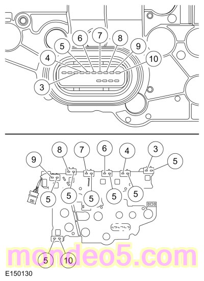
    Transmission internal wiring harness frame pin 5.

    Transmission internal wiring harness frame all pin fives.


Is the resistance less than 3 ohms?

Yes INSTALL a new PCM .
REFER to: Powertrain Control Module (PCM) (303-14B Electronic Engine Controls - 1.6L EcoBoost (132kW/180PS) - Sigma, Removal and Installation).
PERFORM the Transmission Strategy Download, REFER to: Transmission Strategy Download (307-01 Automatic Transmission - Vehicles With: 6-Speed Automatic Transmission - 6F35, General Procedures).
No INSTALL a new transmission internal wiring harness frame.
REFER to: Transmission Internal Wiring Harness Frame (307-01 Automatic Transmission - Vehicles With: 6-Speed Automatic Transmission - 6F35, Removal and Installation).


Diagnostic Overview

Diagnostics in this manual assume a certain skill level and knowledge of Ford-specific diagnostic practices.
REFER to: Diagnostic Methods (100-00 General Information, Description and Operation).


Refer to Wiring Diagrams Cell 29 for schematic and connector information.

TFT Sensor

Normal Operation and Fault Conditions

The TFT sensor is located in the solenoid body leadframe. The resistance value of the TFT sensor varies with temperature change. The PCM monitors the voltage drop across the TFT sensor to determine the temperature of the transmission fluid. When the ignition is turned to the run position, the PCM uses this initial input signal to determine whether a cold start shift schedule is necessary. The cold start shift schedule allows delayed shifts when the transmission fluid is cold. The PCM inhibits TCC operation at low transmission fluid temperatures and adjusts line pressure to temperature.


  DTC Fault Trigger Conditions


DTC Description Fault Trigger Conditions
P0710 Transmission Fluid Temperature Sensor "A" Circuit TFT sensor circuit shorted to ground or open.
P0711 Transmission Fluid Temperature Sensor "A" Circuit Range/Performance TFT sensor indicates a valid temperature but has not changed since start up.
P0712 Transmission Fluid Temperature Sensor "A" Circuit Low TFT sensor circuit short to ground.
P0713 Transmission Fluid Temperature Sensor "A" Circuit High TFT sensor circuit open.
P1711 Transmission Fluid Temperature Sensor Out Of Self Test Range TFT sensor indicates too hot or too cold and must indicate a normal temperature range during the KOER .
P1783 Transmission Overtemperature Condition TFT sensor indicates that the transmission is approaching an overheating condition.


Possible Sources


PINPOINT TEST G G : TRANSMISSION FLUID TEMPERATURE SENSOR
G1 G1   RETRIEVE AND RECORD ALL DTCS
  • Using the diagnostic scan tool, retrieve all Diagnostic Trouble Codes (DTCs).

Are Diagnostic Trouble Codes (DTCs) P0710, P0711, P0712, P0713, P1711 and/or P1783 present?

Yes For Diagnostic Trouble Codes (DTCs) P0710, P0712 and/or P0713, GO to G2 G2
For Diagnostic Trouble Codes (DTCs) P0711, P1711 and/or P1783, GO to G6 G6
No
REFER to: Diagnosis By Symptom (307-01 Automatic Transmission - Vehicles With: 6-Speed Automatic Transmission - 6F35, Diagnosis and Testing).


G2 G2   CHECK THE TFT (TRANSMISSION FLUID TEMPERATURE) SENSOR SIGNAL INPUT
  • Ignition OFF.
  • Disconnect Transmission Vehicle Harness C1520A .
  • Inspect the connector for damaged or pushed-out terminals, corrosion, loose wires and missing or damaged seals.
  • Ignition ON.
  • Enter the following diagnostic mode: TFT and TFTV.

Does the TFT PID display a temperature -39.9 °F ( -40 °C) and the TFTV PID display 4.9 volts?

Yes GO to G5 G5
No REPAIR the circuit.


G3 G3   CHECK THE TFT (TRANSMISSION FLUID TEMPERATURE) SENSOR SIGNAL CIRCUIT
  • Connect.


    Positive Lead Measurement / Action Negative Lead
      C1520A-1   C1520A-2


Does the TFT PID display a temperature 375.5 °F ( 191 °C) and the TFTV PID display 0.0 to 0.2 volts?

Yes GO to G5 G5
No GO to G4 G4


G4 G4   CHECK THE TFT (TRANSMISSION FLUID TEMPERATURE) SENSOR SIGNAL VOLTAGE
  • Measure.


    Positive Lead Measurement / Action Negative Lead
      C1520A-2   Ground


Is the voltage between 4.8 and 5.1 volts?

Yes GO to G5 G5
No INSPECT and REPAIR the circuit. If an open circuit is not found, INSTALL a new PCM .
REFER to: Powertrain Control Module (PCM) (303-14B Electronic Engine Controls - 1.6L EcoBoost (132kW/180PS) - Sigma, Removal and Installation).
PERFORM the Transmission Strategy Download, REFER to: Transmission Strategy Download (307-01 Automatic Transmission - Vehicles With: 6-Speed Automatic Transmission - 6F35, General Procedures).


G5 G5   CHECK THE TFT (TRANSMISSION FLUID TEMPERATURE) SENSOR RESISTANCE
  • Measure.


    Positive Lead Measurement / Action Negative Lead

    Component side resistance pin 1.

    Component side resistance pin 2.


      Temperature


      °F ( °C) Ohms
    -39.9 –-4.0 °F ( -40 –-20 °C) 1,076K-269K
    -2.2 –30.2 °F ( -19 –-1 °C) 309K-91K
    32.0 –68.0 °F ( –20 °C) 104K-35K
    69.8 –103.9 °F ( 21 –40 °C) 40K-15K
    105.7 –157.9 °F ( 41 –70 °C) 17K-4.9K
    159.7 –193.9 °F ( 71 –90 °C) 5.6K-2.5K
    195.7 –229.8 °F ( 91 –110 °C) 3.0K-1.4K
    231.6 –265.8 °F ( 111 –130 °C) 1.7K-0.8K
    267.6 –301.8 °F ( 131 –150 °C) 0.97K-0.56K


Does the temperature to resistance specifications match?

Yes To diagnosis an overheating concern,
REFER to: Transmission Cooling (307-02 Transmission Cooling - Vehicles With: 6-Speed Automatic Transmission - 6F35, Diagnosis and Testing).
No INSTALL a new transmission internal wiring harness frame.
REFER to: Transmission Internal Wiring Harness Frame (307-01 Automatic Transmission - Vehicles With: 6-Speed Automatic Transmission - 6F35, Removal and Installation).


G6 G6   ON DEMAND SELF-TEST
  • Check and make sure the transmission vehicle harness C1520A is fully seated, the terminals are engaged in the connector and in good condition before proceeding.
  • Using the diagnostic scan tool, make sure the transmission fluid temperature is between 33.8 °F ( 1 °C) and 219.1 °F ( 104 °C).
  • Perform the KOER self-test.

Is DTC P0711, P1711 and/or P1783 present?

Yes For Diagnostic Trouble Codes (DTCs) P0711 and P1711, INSTALL a new transmission internal wiring harness frame.
REFER to: Transmission Internal Wiring Harness Frame (307-01 Automatic Transmission - Vehicles With: 6-Speed Automatic Transmission - 6F35, Removal and Installation).
For DTC P1783,
REFER to: Transmission Cooling (307-02 Transmission Cooling - Vehicles With: 6-Speed Automatic Transmission - 6F35, Diagnosis and Testing).
No The system is operating correctly at this time. The concern may have been caused by a loose or corroded connector. ADDRESS the root cause of any connector or terminal issue.


Diagnostic Overview

Diagnostics in this manual assume a certain skill level and knowledge of Ford-specific diagnostic practices.
REFER to: Diagnostic Methods (100-00 General Information, Description and Operation).


Refer to Wiring Diagrams Cell 29 for schematic and connector information.

TCC Solenoid

Normal Operation and Fault Conditions

The PCM controls torque converter lock-up by varying the amount of current applied to the TCC solenoid. When no current is applied to the TCC solenoid, the TCC is fully released. When maximum current is applied, the TCC is fully applied.

NOTE: Without a voltage signal return to the PCM , the transmission solenoid power control relay is commanded off. Using a fused jumper wire between a transmission solenoid control circuit and the signal return circuit, the transmission solenoid power control relay circuit supplies power to the transmission solenoids when the ignition is cycled from off to on. Do not use a solenoid control circuit that may be at fault, refer to DTC Charts for a fault listing.


  DTC Fault Trigger Conditions


DTC Description Fault Trigger Conditions
P0740 Torque Converter Clutch Solenoid Circuit/Open Open circuit in the TCC solenoid or wiring harness.
P0742 Torque Converter Clutch Solenoid Circuit Stuck On Short to ground in the TCC solenoid or wiring harness.
P0743 Torque Converter Clutch Solenoid Circuit Electrical Open or short to ground in the TCC solenoid or wiring harness.
P0744 Torque Converter Clutch Solenoid Circuit Intermittent Short to power in the TCC solenoid or wiring harness.
P2760 Torque Converter Clutch Pressure Control Solenoid Intermittent Intermittent circuit in the TCC solenoid or wiring harness. Open, short to ground or short to power.


Possible Sources


PINPOINT TEST H H : TCC (TORQUE CONVERTER CLUTCH) SOLENOID
H1 H1   RETRIEVE AND RECORD ALL DTCS
  • Using the diagnostic scan tool, retrieve all Diagnostic Trouble Codes (DTCs).

Are Diagnostic Trouble Codes (DTCs) P0740, P0742, P0743, P0744 and/or P2760 present?

Yes For Diagnostic Trouble Codes (DTCs) P0740, P0743 and P2760, GO to H2 H2
For Diagnostic Trouble Codes (DTCs) P0742, P0743 and P2760, GO to H5 H5
For Diagnostic Trouble Codes (DTCs) P0744, GO to H7 H7
No
REFER to: Diagnosis By Symptom (307-01 Automatic Transmission - Vehicles With: 6-Speed Automatic Transmission - 6F35, Diagnosis and Testing).


H2 H2   CHECK THE TCC (TORQUE CONVERTER CLUTCH) SOLENOID CONTROL CIRCUIT FOR AN OPEN
  • Ignition OFF.
  • Disconnect Transmission Vehicle Harness C1520A .
  • Disconnect PCM C1232E .
  • Inspect the connectors for damaged or pushed-out terminals, corrosion, loose wires and missing or damaged seals.
  • Measure.


    Positive Lead Measurement / Action Negative Lead
      C1520A-6   C1232E-10


Is the resistance less than 3 ohms?

Yes GO to H3 H3
No REPAIR the circuit.


H3 H3   CHECK THE TCC (TORQUE CONVERTER CLUTCH) SOLENOID CIRCUIT FOR AN OPEN
  • Measure.


    Positive Lead Measurement / Action Negative Lead

    Component side resistance pin 5.

    Component side resistance pin 6.


Is the resistance between 4.0 and 7.2 ohms?

Yes INSTALL a new PCM .
REFER to: Powertrain Control Module (PCM) (303-14B Electronic Engine Controls - 1.6L EcoBoost (132kW/180PS) - Sigma, Removal and Installation).
PERFORM the Transmission Strategy Download, REFER to: Transmission Strategy Download (307-01 Automatic Transmission - Vehicles With: 6-Speed Automatic Transmission - 6F35, General Procedures).
No GO to H4 H4


H4 H4   CHECK THE TCC (TORQUE CONVERTER CLUTCH) SOLENOID RESISTANCE
  • Remove the transmission internal wiring harness frame.
    REFER to: Transmission Internal Wiring Harness Frame (307-01 Automatic Transmission - Vehicles With: 6-Speed Automatic Transmission - 6F35, Removal and Installation).
    Inspect for metal shavings on the exposed metal contacts or other components and clean the solenoid and transmission internal wiring harness frame terminals.
  • Measure.


    Positive Lead Measurement / Action Negative Lead

    TCC Solenoid pin A.

    TCC Solenoid pin B.


Is the resistance between 4.0 and 7.2 ohms?

Yes INSTALL a new transmission internal wiring harness frame.
REFER to: Transmission Internal Wiring Harness Frame (307-01 Automatic Transmission - Vehicles With: 6-Speed Automatic Transmission - 6F35, Removal and Installation).
No INSTALL a new TCC solenoid.
REFER to: Solenoid (307-01 Automatic Transmission - Vehicles With: 6-Speed Automatic Transmission - 6F35, Removal and Installation).


H5 H5   CHECK THE TCC (TORQUE CONVERTER CLUTCH) SOLENOID CONTROL CIRCUIT FOR A SHORT TO GROUND
  • Ignition OFF.
  • Disconnect Transmission Vehicle Harness C1520A .
  • Disconnect PCM C1232E .
  • Inspect the connectors for damaged or pushed-out terminals, corrosion, loose wires and missing or damaged seals.
  • Measure.


    Positive Lead Measurement / Action Negative Lead
      C1520A-6   Ground


Is the resistance greater than 10,000 ohms?

Yes GO to H6 H6
No REPAIR the circuit.


H6 H6   CHECK THE TCC (TORQUE CONVERTER CLUTCH) SOLENOID FOR A SHORT TO GROUND
  • Remove the transmission internal wiring harness frame.
    REFER to: Transmission Internal Wiring Harness Frame (307-01 Automatic Transmission - Vehicles With: 6-Speed Automatic Transmission - 6F35, Removal and Installation).
    Inspect for metal shavings on the exposed metal contacts or other components and clean the solenoid and transmission internal wiring harness frame terminals.
  • Measure.


    Positive Lead Measurement / Action Negative Lead

    TCC Solenoid pin A.
      Ground


Is the resistance less than 3 ohms?

Yes INSTALL a new TCC solenoid.
REFER to: Solenoid (307-01 Automatic Transmission - Vehicles With: 6-Speed Automatic Transmission - 6F35, Removal and Installation).
No INSTALL a new transmission internal wiring harness frame.
REFER to: Transmission Internal Wiring Harness Frame (307-01 Automatic Transmission - Vehicles With: 6-Speed Automatic Transmission - 6F35, Removal and Installation).


H7 H7   CHECK THE TCC (TORQUE CONVERTER CLUTCH) SOLENOID CONTROL CIRCUIT FOR A SHORT TO POWER
  • Ignition OFF.
  • Disconnect Transmission Vehicle Harness C1520A .
  • Disconnect PCM C1232E .
  • Inspect the connectors for damaged or pushed-out terminals, corrosion, loose wires and missing or damaged seals.
  • Ignition ON.
  • Measure.


    Positive Lead Measurement / Action Negative Lead
      C1520A-6   Ground


Is any voltage present?

Yes REPAIR the circuit.
No INSTALL a new PCM .
REFER to: Powertrain Control Module (PCM) (303-14B Electronic Engine Controls - 1.6L EcoBoost (132kW/180PS) - Sigma, Removal and Installation).
PERFORM the Transmission Strategy Download, REFER to: Transmission Strategy Download (307-01 Automatic Transmission - Vehicles With: 6-Speed Automatic Transmission - 6F35, General Procedures).


Diagnostic Overview

Diagnostics in this manual assume a certain skill level and knowledge of Ford-specific diagnostic practices.
REFER to: Diagnostic Methods (100-00 General Information, Description and Operation).


Refer to Wiring Diagrams Cell 29 for schematic and connector information.

Pressure Control Solenoid A (PCA)

Normal Operation and Fault Conditions

The PCM controls the hydraulic line pressure by varying the amount of current applied to the Pressure Control Solenoid A (PCA), (Line Pressure Control (LPC)) solenoid. When no current is applied to the Pressure Control Solenoid A (PCA), the Pressure Control Solenoid A (PCA) is fully opened, resulting in the maximum amount of hydraulic pressure to the main pressure regulator valve. When maximum current is applied, the Pressure Control Solenoid A (PCA) is fully closed, resulting in minimum pressure to the main pressure regulator valve.

NOTE: Without a voltage signal return to the PCM , the transmission solenoid power control relay is commanded off. Using a fused jumper wire between a transmission solenoid control circuit and the signal return circuit, the transmission solenoid power control relay circuit supplies power to the transmission solenoids when the ignition is cycled from off to on. Do not use a solenoid control circuit that may be at fault, refer to DTC Charts for a fault listing.


  DTC Fault Trigger Conditions


DTC Description Fault Trigger Conditions
P0748 Pressure Control Solenoid "A" Electrical Pressure control solenoid electrical circuit general fault. May set along with DTC P0960, P0962 and P0963.
P0960 Pressure Control Solenoid "A" Control Circuit/Open Open circuit in solenoid or solenoid circuitry.
P0961 Pressure Control Solenoid "A" Control Circuit Range/Performance Intermittent short to ground in solenoid or solenoid circuitry.
P0962 Pressure Control Solenoid "A" Control Circuit Low Short to ground in solenoid or solenoid circuitry.
P0963 Pressure Control Solenoid "A" Control Circuit High Short to power in solenoid circuitry.


Possible Sources


PINPOINT TEST I I : PRESSURE CONTROL SOLENOID A (PCA)
I1 I1   RETRIEVE AND RECORD ALL DTCS
  • Using the diagnostic scan tool, retrieve all Diagnostic Trouble Codes (DTCs).

Are Diagnostic Trouble Codes (DTCs) P0748, P0960, P0961, P0962 and/or P0963 present?

Yes For Diagnostic Trouble Codes (DTCs) P0748 and P0960, GO to I2 I2
For Diagnostic Trouble Codes (DTCs) P0748, P0961 and P0962, GO to I5 I5
For Diagnostic Trouble Codes (DTCs) P0748 and P0963, GO to I7 I7
No
REFER to: Diagnosis By Symptom (307-01 Automatic Transmission - Vehicles With: 6-Speed Automatic Transmission - 6F35, Diagnosis and Testing).


I2 I2   CHECK THE PRESSURE CONTROL SOLENOID A (PCA) CONTROL CIRCUIT FOR AN OPEN
  • Ignition OFF.
  • Disconnect Transmission Vehicle Harness C1520A .
  • Disconnect PCM C1232E .
  • Inspect the connectors for damaged or pushed-out terminals, corrosion, loose wires and missing or damaged seals.
  • Measure.


    Positive Lead Measurement / Action Negative Lead
      C1520A-3   C1232E-59


Is the resistance less than 3 ohms?

Yes GO to I3 I3
No REPAIR the circuit.


I3 I3   CHECK THE PRESSURE CONTROL SOLENOID A (PCA) FOR AN OPEN
  • Measure.


    Positive Lead Measurement / Action Negative Lead

    Component side resistance pin 5.

    Component side resistance pin 3.


Is the resistance between 4.0 and 7.2 ohms?

Yes INSTALL a new PCM .
REFER to: Powertrain Control Module (PCM) (303-14B Electronic Engine Controls - 1.6L EcoBoost (132kW/180PS) - Sigma, Removal and Installation).
PERFORM the Transmission Strategy Download, REFER to: Transmission Strategy Download (307-01 Automatic Transmission - Vehicles With: 6-Speed Automatic Transmission - 6F35, General Procedures).
No GO to I4 I4


I4 I4   CHECK THE PRESSURE CONTROL SOLENOID A (PCA) RESISTANCE
  • Remove the transmission internal wiring harness frame.
    REFER to: Transmission Internal Wiring Harness Frame (307-01 Automatic Transmission - Vehicles With: 6-Speed Automatic Transmission - 6F35, Removal and Installation).
    Inspect for metal shavings on the exposed metal contacts or other components and clean the solenoid and transmission internal wiring harness frame terminals.
  • Measure.


    Positive Lead Measurement / Action Negative Lead

    Pressure Control Solenoid A (PCA) pin A.

    Pressure Control Solenoid A (PCA) pin B.


Is the resistance between 4.0 and 7.2 ohms?

Yes INSTALL a new transmission internal wiring harness frame.
REFER to: Transmission Internal Wiring Harness Frame (307-01 Automatic Transmission - Vehicles With: 6-Speed Automatic Transmission - 6F35, Removal and Installation).
No INSTALL a new Pressure Control Solenoid A (PCA).
REFER to: Solenoid (307-01 Automatic Transmission - Vehicles With: 6-Speed Automatic Transmission - 6F35, Removal and Installation).


I5 I5   CHECK THE PRESSURE CONTROL SOLENOID A (PCA) CONTROL CIRCUIT FOR A SHORT TO GROUND
  • Ignition OFF.
  • Disconnect Transmission Vehicle Harness C1520A .
  • Disconnect PCM C1232E .
  • Inspect the connectors for damaged or pushed-out terminals, corrosion, loose wires and missing or damaged seals.
  • Measure.


    Positive Lead Measurement / Action Negative Lead
      C1520A-3   Ground


Is the resistance greater than 10,000 ohms?

Yes GO to I6 I6
No REPAIR the circuit.


I6 I6   CHECK THE PRESSURE CONTROL SOLENOID A (PCA) FOR A SHORT TO GROUND
  • Remove the transmission internal wiring harness frame.
    REFER to: Transmission Internal Wiring Harness Frame (307-01 Automatic Transmission - Vehicles With: 6-Speed Automatic Transmission - 6F35, Removal and Installation).
    Inspect for metal shavings on the exposed metal contacts or other components and clean the solenoid and transmission internal wiring harness frame terminals.
  • Measure.


    Positive Lead Measurement / Action Negative Lead

    Pressure Control Solenoid A (PCA) pin A.
      Ground


Is the resistance less than 3 ohms?

Yes INSTALL a new Pressure Control Solenoid A (PCA).
REFER to: Solenoid (307-01 Automatic Transmission - Vehicles With: 6-Speed Automatic Transmission - 6F35, Removal and Installation).
No INSTALL a new transmission internal wiring harness frame.
REFER to: Transmission Internal Wiring Harness Frame (307-01 Automatic Transmission - Vehicles With: 6-Speed Automatic Transmission - 6F35, Removal and Installation).


I7 I7   CHECK THE PRESSURE CONTROL SOLENOID A (PCA) FOR A SHORT TO VOLTAGE
  • Ignition OFF.
  • Disconnect Transmission Vehicle Harness C1520A .
  • Disconnect PCM C1232E .
  • Inspect the connectors for damaged or pushed-out terminals, corrosion, loose wires and missing or damaged seals.
  • Measure.


    Positive Lead Measurement / Action Negative Lead
      C1520A-3   Ground


Is any voltage present?

Yes REPAIR the circuit.
No INSTALL a new PCM .
REFER to: Powertrain Control Module (PCM) (303-14B Electronic Engine Controls - 1.6L EcoBoost (132kW/180PS) - Sigma, Removal and Installation).
PERFORM the Transmission Strategy Download, REFER to: Transmission Strategy Download (307-01 Automatic Transmission - Vehicles With: 6-Speed Automatic Transmission - 6F35, General Procedures).


Diagnostic Overview

Diagnostics in this manual assume a certain skill level and knowledge of Ford-specific diagnostic practices.
REFER to: Diagnostic Methods (100-00 General Information, Description and Operation).


Refer to Wiring Diagrams Cell 29 for schematic and connector information.

TR Sensor

Normal Operation and Fault Conditions

The TR sensor provides a fixed frequency duty cycle to the PCM for each manual control lever positions (PARK, REVERSE, NEUTRAL, DRIVE and LOW). The PCM uses the TR sensor signal for Line Pressure Control (LPC), shift scheduling and TCC operation. The PCM transmits TR data on the High Speed (HS) CAN to the BCM for engine start and reverse lamp operation.


  DTC Fault Trigger Conditions


DTC Description Fault Trigger Conditions
P0706 Transmission Range Sensor "A" Circuit Range/Performance Mechanical or electrical fault. Input from the TR sensor did not change or is intermittent.
P0707 Transmission Range Sensor "A" Circuit Low TR sensor circuit open or short to ground.
P0708 Transmission Range Sensor "A" Circuit High TR sensor circuit open.
P1702 Transmission Range Sensor "A" Circuit Intermittent TR sensor circuit open or short to ground.
P1705 Transmission Range Sensor Not Indicating Park/Neutral During Self-Test TR sensor misaligned or in wrong position during the self-test.
P1921 Transmission Range Signal The PCM has detected a TR signal duty cycle out of range.


Possible Sources


PINPOINT TEST J J : TR (TRANSMISSION RANGE) SENSOR
J1 J1   RETRIEVE AND RECORD ALL DTCS
  • Using the diagnostic scan tool, retrieve all Diagnostic Trouble Codes (DTCs).

Are Diagnostic Trouble Codes (DTCs) P0706, P0707, P0708, P1702, P1705 and/or P1921 present?

Yes For Diagnostic Trouble Codes (DTCs) P0706, P0708, P1702 and/or P1921, GO to J2 J2
For DTC P1705, GO to J9 J9
No
REFER to: Diagnosis By Symptom (307-01 Automatic Transmission - Vehicles With: 6-Speed Automatic Transmission - 6F35, Diagnosis and Testing).


J2 J2   VERIFY SELECTOR LEVER CABLE/LINKAGE ADJUSTMENT
  • Verify the selector lever cable/linkage is correctly adjusted.
    REFER to: Selector Lever Cable Adjustment (307-05 Automatic Transmission External Controls, General Procedures).

Is the selector lever cable/linkage is correctly adjusted?

Yes GO to J3 J3
No VERIFY the selector lever cable/ linkage adjustment.
REFER to: Selector Lever Cable Adjustment (307-05 Automatic Transmission External Controls, General Procedures).
REPEAT the self-test. If the TR sensor Diagnostic Trouble Codes (DTCs) return, GO to J3 J3


J3 J3   CHECK THE TR (TRANSMISSION RANGE) SENSOR CIRCUITS FOR AN OPEN
  • Ignition OFF.
  • Disconnect Transmission Vehicle Harness C1520A .
  • Disconnect PCM C1232E .
  • Inspect the connectors for damaged or pushed-out terminals, corrosion, loose wires and missing or damaged seals.
  • Measure.


    Positive Lead Measurement / Action Negative Lead
      C1520A-17   C1232E-10
      C1520A-18   C1232E-22
      C1520A-20   C1232E-32


Is the resistance less than 3 ohms?

Yes GO to J4 J4
No REPAIR the circuit.


J4 J4   CHECK THE TR (TRANSMISSION RANGE) SENSOR CIRCUITS FOR A SHORT TO GROUND
  • Disconnect Transmission Vehicle Harness C1520B .
  • Inspect the connector for damaged or pushed-out terminals, corrosion, loose wires and missing or damaged seals.
  • Measure.


    Positive Lead Measurement / Action Negative Lead
      C1520A-17   Ground
      C1520A-18   Ground
      C1520A-20   Ground


Is the resistance greater than 10,000 ohms?

Yes GO to J5 J5
No REPAIR the circuit.


J5 J5   CHECK THE TR (TRANSMISSION RANGE) SENSOR CIRCUITS FOR A SHORT TO VOLTAGE
  • Ignition ON.
  • Measure.


    Positive Lead Measurement / Action Negative Lead
      C1520A-17   Ground
      C1520A-18   Ground
      C1520A-20   Ground


Is any voltage present?

Yes REPAIR the circuit.
No GO to J6 J6


J6 J6   CHECK THE TR (TRANSMISSION RANGE) SENSOR CIRCUITS FOR A SHORT TOGETHER
  • Ignition OFF.
  • Measure.


    Positive Lead Measurement / Action Negative Lead
      C1520A-20   C1520A-18
      C1520A-20   C1520A-17
      C1520A-18   C1520A-17


Are all of the resistances greater than 10,000 ohms?

Yes GO to J7 J7
No REPAIR the circuits.


J7 J7   CHECK THE TR (TRANSMISSION RANGE) SENSOR CIRCUITS IN THE TRANSMISSION INTERNAL WIRING HARNESS FRAME FOR AN OPEN
  • Remove the main control cover.
    REFER to: Main Control Cover (307-01 Automatic Transmission - Vehicles With: 6-Speed Automatic Transmission - 6F35, Removal and Installation).
  • Disconnect TR Sensor.
  • Inspect the connector for damaged or pushed-out terminals, corrosion, loose wires and missing or damaged seals.
  • Measure.


    Positive Lead Measurement / Action Negative Lead

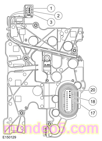
    Component side resistance pins 18, 17 and 20.

    Component side resistance pins 1, 2 and 3.


Is the resistance less than 3 ohms?

Yes GO to J8 J8
No INSTALL a new transmission internal wiring harness frame.
REFER to: Transmission Internal Wiring Harness Frame (307-01 Automatic Transmission - Vehicles With: 6-Speed Automatic Transmission - 6F35, Removal and Installation).


J8 J8   CHECK FOR VOLTAGE AND GROUND AT THE TR (TRANSMISSION RANGE) SENSOR
  • Connect PCM C1232E .
  • Connect Transmission Vehicle Harness C1520B .
  • Connect Transmission Vehicle Harness C1520A .
  • Ignition ON.
  • Measure.


    Positive Lead Measurement / Action Negative Lead

    TR sensor voltage supply pin 1.

    TR sensor ground pin 3.


Is the voltage greater than 10 volts?

Yes INSTALL a new TR sensor.
REFER to: Transmission Range (TR) Sensor (307-01 Automatic Transmission - Vehicles With: 6-Speed Automatic Transmission - 6F35, Removal and Installation).
No CHECK OASIS for applicable Technical Service Bulletins (TSBs). If a TSB exists for this concern, discontinue this test and follow the TSB instructions. If no Technical Service Bulletins (TSBs) address this concern, INSTALL a new PCM .
REFER to: Powertrain Control Module (PCM) (303-14B Electronic Engine Controls - 1.6L EcoBoost (132kW/180PS) - Sigma, Removal and Installation).
PERFORM the Transmission Strategy Download, REFER to: Transmission Strategy Download (307-01 Automatic Transmission - Vehicles With: 6-Speed Automatic Transmission - 6F35, General Procedures).


J9 J9   ON DEMAND SELF-TEST
  • Check to make sure the transmission harness connector is fully seated, terminals are engaged in connector and in good condition before proceeding.
  • Make sure the selector lever is in the Park or Neutral position.
  • Using the diagnostic scan tool, perform the KOEO self-test.

Did DTC P1705 return?

Yes VERIFY selector lever cable adjustment.
REFER to: Selector Lever Cable Adjustment (307-05 Automatic Transmission External Controls, General Procedures).
No The system is operating correctly at this time. The concern may have been caused by a loose or corroded connector. ADDRESS the root cause of any connector or terminal issues.


Diagnostic Overview

Diagnostics in this manual assume a certain skill level and knowledge of Ford-specific diagnostic practices.
REFER to: Diagnostic Methods (100-00 General Information, Description and Operation).


Refer to Wiring Diagrams Cell 29 for schematic and connector information.

TSS Sensor

Normal Operation and Fault Conditions

The TSS sensor is a Hall-effect sensor that sends a signal to the PCM that indicates transmission turbine shaft input speed. The TSS sensor provides converter turbine speed information for TCC strategy.


  DTC Fault Trigger Conditions


DTC Description Fault Trigger Conditions
P0715 Turbine/Input Shaft Speed Sensor "A" Circuit No input from the TSS sensor.
P0717 Turbine/Input Shaft Speed Sensor "A" Circuit No Signal No input from the TSS sensor.
P0718 Turbine/Input Shaft Speed Sensor "A" Circuit Intermittent Unrealistic change in the TSS sensor signal, erratic or intermittently no input.


Possible Sources


PINPOINT TEST K K : TSS (TURBINE SHAFT SPEED) SENSOR
K1 K1   RETRIEVE AND RECORD ALL DTCS
  • Using the diagnostic scan tool, retrieve all Diagnostic Trouble Codes (DTCs).

Are Diagnostic Trouble Codes (DTCs) P0715, P0717, P0718 and/or P0720 present?

Yes For Diagnostic Trouble Codes (DTCs) P0715, P0717 and P0718, GO to K2 K2
For DTC P0715 and P0720, GO to K6 K6
No
REFER to: Diagnosis By Symptom (307-01 Automatic Transmission - Vehicles With: 6-Speed Automatic Transmission - 6F35, Diagnosis and Testing).


K2 K2   CHECK THE TSS (TURBINE SHAFT SPEED) SENSOR SIGNAL CIRCUIT FOR AN OPEN
  • Ignition OFF.
  • Disconnect Transmission Vehicle Harness C1520B .
  • Disconnect PCM C1232E .
  • Inspect the connectors for damaged or pushed-out terminals, corrosion, loose wires and missing or damaged seals.
  • Measure.


    Positive Lead Measurement / Action Negative Lead
      C1520B-2   C1232E-27


Is the resistance less than 3 ohms?

Yes GO to K3 K3
No REPAIR the circuit.


K3 K3   CHECK THE TSS (TURBINE SHAFT SPEED) SENSOR SIGNAL CIRCUIT FOR A SHORT TO GROUND
  • Measure.


    Positive Lead Measurement / Action Negative Lead
      C1520B-2   Ground


Is the resistance greater than 10,000 ohms?

Yes GO to K4 K4
No REPAIR the circuit.


K4 K4   CHECK THE TSS (TURBINE SHAFT SPEED) SENSOR SIGNAL CIRCUIT FOR A SHORT TO POWER
  • Ignition ON.
  • Measure.


    Positive Lead Measurement / Action Negative Lead
      C1520B-2   Ground


Is any voltage present?

Yes REPAIR the circuit.
No GO to K5 K5


K5 K5   CHECK THE TSS (TURBINE SHAFT SPEED) SENSOR GROUND CIRCUIT
  • Ignition OFF.
  • Connect PCM C1232E .
  • Ignition ON.
  • Measure.


    Positive Lead Measurement / Action Negative Lead
      C1520B-3   C1520B-1


Is voltage less than 4.8 volts?

Yes INSPECT and REPAIR the circuit. If an open circuit is not found, INSTALL a new PCM .
REFER to: Powertrain Control Module (PCM) (303-14B Electronic Engine Controls - 1.6L EcoBoost (132kW/180PS) - Sigma, Removal and Installation).
PERFORM the Transmission Strategy Download, REFER to: Transmission Strategy Download (307-01 Automatic Transmission - Vehicles With: 6-Speed Automatic Transmission - 6F35, General Procedures).
No INSTALL a new TSS .
REFER to: Turbine Shaft Speed (TSS) Sensor (307-01 Automatic Transmission - Vehicles With: 6-Speed Automatic Transmission - 6F35, Removal and Installation).


K6 K6   CHECK THE TSS (TURBINE SHAFT SPEED) SENSOR VEHICLE POWER CIRCUIT FOR AN OPEN
  • Ignition OFF.
  • Disconnect Transmission Vehicle Harness C1520B .
  • Inspect the connector for damaged or pushed-out terminals, corrosion, loose wires and missing or damaged seals.
  • Ignition ON.
  • Measure.


    Positive Lead Measurement / Action Negative Lead
      C1520B-3   Ground


Is the voltage less than 9.5 volts?

Yes INSPECT and REPAIR the circuit. If an open circuit is not found, INSTALL a new PCM .
REFER to: Powertrain Control Module (PCM) (303-14B Electronic Engine Controls - 1.6L EcoBoost (132kW/180PS) - Sigma, Removal and Installation).
PERFORM the Transmission Strategy Download, REFER to: Transmission Strategy Download (307-01 Automatic Transmission - Vehicles With: 6-Speed Automatic Transmission - 6F35, General Procedures).
No CLEAR the DTC . If Diagnostic Trouble Codes (DTCs) P0715 and/or P0720 return, INSTALL a new PCM .
REFER to: Powertrain Control Module (PCM) (303-14B Electronic Engine Controls - 1.6L EcoBoost (132kW/180PS) - Sigma, Removal and Installation).
PERFORM the Transmission Strategy Download, REFER to: Transmission Strategy Download (307-01 Automatic Transmission - Vehicles With: 6-Speed Automatic Transmission - 6F35, General Procedures).


Diagnostic Overview

Diagnostics in this manual assume a certain skill level and knowledge of Ford-specific diagnostic practices.
REFER to: Diagnostic Methods (100-00 General Information, Description and Operation).


Refer to Wiring Diagrams Cell 29 for schematic and connector information.

OSS Sensor

Normal Operation and Fault Conditions

The OSS sensor is a Hall-effect sensor that sends a signal to the PCM that indicates transmission output shaft speed. The OSS sensor is used for TCC control and shift scheduling.


  DTC Fault Trigger Conditions


DTC Description Fault Trigger Conditions
P0720 Output Shaft Speed Sensor Circuit No input from the OSS sensor.
P0721 Output Shaft Speed Sensor Circuit Range/Performance Unrealistic change in the OSS sensor signal, erratic or intermittently no input.
P0722 Output Shaft Speed Sensor Circuit No Signal No input from the OSS sensor.


Possible Sources


PINPOINT TEST L L : OSS (OUTPUT SHAFT SPEED) SENSOR
L1 L1   RETRIEVE AND RECORD ALL DTCS
  • Using the diagnostic scan tool, retrieve all Diagnostic Trouble Codes (DTCs).

Are Diagnostic Trouble Codes (DTCs) P0720, P0721, P0722 and/or P0715, present?

Yes For Diagnostic Trouble Codes (DTCs) P0720, P0721 and P0722, GO to L2 L2
For DTC P0715 and P0720, GO to L6 L6
No
REFER to: Diagnosis By Symptom (307-01 Automatic Transmission - Vehicles With: 6-Speed Automatic Transmission - 6F35, Diagnosis and Testing).


L2 L2   CHECK THE OSS (OUTPUT SHAFT SPEED) SENSOR SIGNAL CIRCUIT FOR AN OPEN
  • Ignition OFF.
  • Disconnect Transmission Vehicle Harness C1520A .
  • Disconnect PCM C1232E .
  • Inspect the connectors for damaged or pushed-out terminals, corrosion, loose wires and missing or damaged seals.
  • Measure.


    Positive Lead Measurement / Action Negative Lead
      C1520A-19   C1232E-12


Is the resistance less than 3 ohms?

Yes GO to L3 L3
No REPAIR the circuit.


L3 L3   CHECK THE OSS (OUTPUT SHAFT SPEED) SENSOR SIGNAL CIRCUIT FOR A SHORT TO GROUND
  • Measure.


    Positive Lead Measurement / Action Negative Lead
      C1520A-19   Ground


Is the resistance greater than 10,000 ohms?

Yes REPAIR the circuit.
No GO to L4 L4


L4 L4   CHECK THE OSS (OUTPUT SHAFT SPEED) SENSOR SIGNAL CIRCUIT FOR A SHORT TO POWER
  • Ignition ON.
  • Measure.


    Positive Lead Measurement / Action Negative Lead
      C1520A-19   Ground


Is any voltage present?

Yes REPAIR the circuit.
No GO to L5 L5


L5 L5   CHECK THE OSS (OUTPUT SHAFT SPEED) SENSOR GROUND CIRCUIT
  • Ignition OFF.
  • Connect PCM C1232E .
  • Ignition ON.
  • Measure.


    Positive Lead Measurement / Action Negative Lead
      C1520A-18   C1520A-20


Is voltage less than 4.8 volts?

Yes INSPECT and REPAIR the circuit. If an open circuit is not found, INSTALL a new PCM .
REFER to: Powertrain Control Module (PCM) (303-14B Electronic Engine Controls - 1.6L EcoBoost (132kW/180PS) - Sigma, Removal and Installation).
PERFORM the Transmission Strategy Download, REFER to: Transmission Strategy Download (307-01 Automatic Transmission - Vehicles With: 6-Speed Automatic Transmission - 6F35, General Procedures).
No INSTALL a new OSS sensor.
REFER to: Output Shaft Speed (OSS) Sensor (307-01 Automatic Transmission - Vehicles With: 6-Speed Automatic Transmission - 6F35, Removal and Installation).


L6 L6   CHECK THE OSS (OUTPUT SHAFT SPEED) SENSOR VEHICLE POWER CIRCUIT FOR AN OPEN
  • Ignition OFF.
  • Disconnect Transmission Vehicle Harness C1520A .
  • Inspect the connector for damaged or pushed-out terminals, corrosion, loose wires and missing or damaged seals.
  • Ignition ON.
  • Measure.


    Positive Lead Measurement / Action Negative Lead
      C1520A-18   Ground


Is voltage less than 9.5 volts?

Yes INSPECT and REPAIR the circuit. If an open circuit is not found, INSTALL a new PCM .
REFER to: Powertrain Control Module (PCM) (303-14B Electronic Engine Controls - 1.6L EcoBoost (132kW/180PS) - Sigma, Removal and Installation).
PERFORM the Transmission Strategy Download, REFER to: Transmission Strategy Download (307-01 Automatic Transmission - Vehicles With: 6-Speed Automatic Transmission - 6F35, General Procedures).
No CLEAR the DTC . If Diagnostic Trouble Codes (DTCs) P0715 and/or P0720 return, INSTALL a new PCM .
REFER to: Powertrain Control Module (PCM) (303-14B Electronic Engine Controls - 1.6L EcoBoost (132kW/180PS) - Sigma, Removal and Installation).
PERFORM the Transmission Strategy Download, REFER to: Transmission Strategy Download (307-01 Automatic Transmission - Vehicles With: 6-Speed Automatic Transmission - 6F35, General Procedures).


Diagnostic Overview

Diagnostics in this manual assume a certain skill level and knowledge of Ford-specific diagnostic practices.
REFER to: Diagnostic Methods (100-00 General Information, Description and Operation).


Refer to Wiring Diagrams Cell 40 for schematic and connector information.

Transmission Fluid Pump

Normal Operation and Fault Conditions

The electronic transmission fluid auxiliary pump is used to keep the transmission engaged when the engine is stopped and the transmission is in drive. The electronic transmission fluid auxiliary pump has an internal microprocesser and communicates with the PCM over a PWM circuit with a frequency of 150 Hz with a duty cycle range of 10% to 90%.


  DTC Fault Trigger Conditions


DTC Description Fault Trigger Conditions
P0C27 Electric Transmission Fluid Pump Motor Current Low This DTC sets if the E-pump communication is ok. The frequency is between 130 Hz and 170 Hz but a low current is detected (10% to 15% duty cycle).
P0C28 Electric Transmission Fluid Pump Motor Current High This DTC sets if the E-pump communication is ok. The frequency is between 130 Hz and 170 Hz but a low current is detected (20% to 25% duty cycle).
P0C2C Electric Transmission Fluid Pump Control Module Feedback Signal Range/Performance This DTC sets if the E-pump communication is ok. The frequency is between 130 Hz and 170 Hz but the duty cycle does not match one of the defined duty cycle ranges.
P0C2D Electric Transmission Fluid Pump Control Module Feedback Signal Low This DTC sets if the duty cycle is less than 10%.
P0C2E Electric Transmission Fluid Pump Control Module Feedback Signal High This DTC sets if the duty cycle is greater than 90%.
P175A Transmission Fluid Over Temperature Condition - Electric Transmission Fluid Pump Disabled This DTC sets if the E-pump communication is ok. The frequency is between 130 Hz and 170 Hz but an over temperature condition is detected (30% to 34% duty cycle).
P2796 Electric Transmission Fluid Pump Control Circuit This DTC sets when the E-pump is not receiving a signal on it's PWM input signal from the PCM .


Possible Sources


PINPOINT TEST M M : TRANSMISSION FLUID AUXILIARY PUMP
M1 M1   RETRIEVE AND RECORD ALL DTCS
  • Using the diagnostic scan tool, retrieve all Diagnostic Trouble Codes (DTCs).

Are Diagnostic Trouble Codes (DTCs) P0C27, P0C28, P0C2C, P0C2D, P0C2E, P175A and/or P2796 present?

Yes For Diagnostic Trouble Codes (DTCs) P0C27, P0C28, P0C2C, P0C2D, P0C2E, P175A, GO to M2 M2
For DTC P2796, GO to M7 M7
No The system is operating correctly at this time. The concern may have been caused by a loose or corroded connector. ADDRESS the root cause of any connector or terminal issues.


M2 M2   CHECK THE TRANSMISSION FLUID AUXILIARY PUMP POWER CIRCUITS
  • Ignition OFF.
  • Disconnect Transmission Fluid Auxiliary Pump C1717 .
  • Ignition ON.
  • Measure.


    Positive Lead Measurement / Action Negative Lead
      C1717-1   Ground
      C1717-2   Ground


Is voltage greater than 10 volts?

Yes GO to M4 M4
No GO to M3 M3


M3 M3   CHECK THE TRANSMISSION FLUID AUXILIARY PUMP POWER CIRCUITS FOR AN OPEN
  • Ignition OFF.
  • Disconnect BJB C1035B .
  • Measure.


    Positive Lead Measurement / Action Negative Lead
      C1035-54   C1717-1
      C1035-17   C1717-2


Is the resistance less than 3 ohms?

Yes GO to M4 M4
No REPAIR the circuit.


M4 M4   CHECK THE TRANSMISSION FLUID AUXILIARY PUMP GROUND CIRCUIT FOR AN OPEN
  • Measure.


    Positive Lead Measurement / Action Negative Lead
      C1717-5   Ground


Is the resistance less than 3 ohms?

Yes GO to M5 M5
No REPAIR the circuit.


M5 M5   CHECK THE TRANSMISSION FLUID AUXILIARY PUMP SPEED COMMAND CIRCUIT FOR AN OPEN
  • Measure.


    Positive Lead Measurement / Action Negative Lead
      C1717-4   C1232E-79


Is the resistance less than 3 ohms?

Yes GO to M6 M6
No REPAIR the circuit.


M6 M6   CHECK THE TRANSMISSION FLUID AUXILIARY PUMP SPEED COMMAND CIRCUIT FOR A SHORT TO GROUND
  • Measure.


    Positive Lead Measurement / Action Negative Lead
      C1717-4   Ground


Is the resistance greater than 10,000 ohms?

Yes INSTALL a new transmission fluid auxiliary pump.
REFER to: Transmission Fluid Auxiliary Pump (307-01 Automatic Transmission - Vehicles With: 6-Speed Automatic Transmission - 6F35, Removal and Installation).
No REPAIR the circuit.


M7 M7   CHECK THE TRANSMISSION FLUID AUXILIARY PUMP PWM (PULSE WIDTH MODULATION) CIRCUIT FOR AN OPEN
  • Disconnect PCM C1232E .
  • Measure.


    Positive Lead Measurement / Action Negative Lead
      C1717-5   C1232E-81


Is the resistance less than 3 ohms?

Yes GO to M8 M8
No REPAIR the circuit.


M8 M8   CHECK THE TRANSMISSION FLUID AUXILIARY PUMP PWM (PULSE WIDTH MODULATION) CIRCUIT FOR A SHORT TO GROUND
  • Measure.


    Positive Lead Measurement / Action Negative Lead
      C1717-5   Ground


Is the resistance greater than 10,000 ohms?

Yes INSTALL a new PCM .
REFER to: Powertrain Control Module (PCM) (303-14B Electronic Engine Controls - 1.6L EcoBoost (132kW/180PS) - Sigma, Removal and Installation).
No REPAIR the circuit.