| 417-01 Exterior Lighting
|
2013 - 2014 Fusion
|
| Diagnosis and Testing
|
Procedure revision date:
04/25/2013
|
Headlamps
DTC Chart: Body Control Module (BCM)
Diagnostics in this manual assume a certain skill level and knowledge of Ford-specific diagnostic practices.
REFER to:
Diagnostic Methods
(100-00 General Information, Description and Operation).
Chart
DTC Chart: Steering Column Control Module (SCCM)
Diagnostics in this manual assume a certain skill level and knowledge of Ford-specific diagnostic practices.
REFER to:
Diagnostic Methods
(100-00 General Information, Description and Operation).
Chart
|
DTC
|
Description
|
Action
|
|
B1007:09
|
High-Beam Headlamp Switch: Component Failure
|
INSTALL a new
steering column multifunction switch.
REFER to:
Steering Column Multifunction Switch LH
(211-05 Steering Wheel and Column Electrical Components, Removal and Installation).
TEST the system for normal operation. If the concern still exists, INSTALL a new
.
REFER to:
Steering Column Control Module (SCCM)
(211-05 Steering Wheel and Column Electrical Components, Removal and Installation).
|
DTC Chart: Image Processing Module - A (IPM-A)
Diagnostics in this manual assume a certain skill level and knowledge of Ford-specific diagnostic practices.
REFER to:
Diagnostic Methods
(100-00 General Information, Description and Operation).
Chart
|
DTC
|
Description
|
Action
|
|
B11C7:46
|
High Beam Sensor: Calibration / Parameter Memory Failure
|
GO to Pinpoint Test F
|
|
B11C7:97
|
High Beam Sensor: Component or System Operation Obstructed or Blocked
|
GO to Pinpoint Test F
|
Symptom Chart(s)
Symptom Chart: Headlamps
Diagnostics in this manual assume a certain skill level and knowledge of Ford-specific diagnostic practices.
REFER to:
Diagnostic Methods
(100-00 General Information, Description and Operation).
Symptom Chart
|
Condition
|
Possible Sources
|
Actions
|
|
A module does not respond to the scan tool
|
-
Fuse
-
Wiring, terminals or connectors
-
Module
|
REFER to:
Communications Network
(418-00 Module Communications Network, Diagnosis and Testing).
|
|
The headlamp exit delay feature is inoperative
|
|
CHECK the flash-to-pass function. If the flash-to-pass is inoperative,
GO to Pinpoint Test E
If the flash-to-pass operates, INSTALL a new
.
REFER to:
Body Control Module (BCM)
(419-10 Multifunction Electronic Modules, Removal and Installation).
|
|
One or both low beams is inoperative
|
Refer to the Pinpoint Test
|
VERIFY the bulb(s) are OK. If OK,
GO to Pinpoint Test A
|
|
One or both high beams is inoperative
|
Refer to the Pinpoint Test
|
VERIFY the bulb(s) are OK. If OK,
GO to Pinpoint Test B
|
|
One or both low beams are on continuously
|
Refer to the Pinpoint Test
|
GO to Pinpoint Test C
|
|
One or both high beams are on continuously
|
Refer to the Pinpoint Test
|
GO to Pinpoint Test D
|
|
The flash-to-pass feature is inoperative
|
Refer to the Pinpoint Test
|
GO to Pinpoint Test E
|
|
The automatic high beam feature is inoperative
|
Refer to the Pinpoint Test
|
GO to Pinpoint Test F
|
Symptom Chart: Daytime Running Lamps (DRL)
Diagnostics in this manual assume a certain skill level and knowledge of Ford-specific diagnostic practices.
REFER to:
Diagnostic Methods
(100-00 General Information, Description and Operation).
Symptom Chart
|
Condition
|
Possible Sources
|
Actions
|
|
A module does not respond to the scan tool
|
-
Fuse
-
Wiring, terminals or connectors
-
Module
|
REFER to:
Communications Network
(418-00 Module Communications Network, Diagnosis and Testing).
|
|
The Daytime Running Lamps (DRL) are inoperative
|
Refer to the Pinpoint Test
|
GO to Pinpoint Test G
|
Pinpoint Tests
One Or Both Low Beams is Inoperative
Refer to Wiring Diagrams Cell 85 for schematic and connector information.
Normal Operation and Fault Conditions
REFER to:
Exterior Lighting - System Operation and Component Description
(417-01 Exterior Lighting, Description and Operation).
Fault Trigger Conditions
|
DTC
|
Description
|
Fault Trigger Conditions
|
|
B1D00:11
|
Left Low Beam: Circuit Short To Ground
|
Sets when the
detects a short to ground from the left low beam output circuit.
|
|
B1D00:15
|
Left Low Beam: Circuit Short To Battery Or Open
|
Sets when the
detects an open from the left low beam output circuit.
|
|
B1D01:11
|
Right Low Beam: Circuit Short To Ground
|
Sets when the
detects a short to ground from the right low beam output circuit.
|
|
B1D01:15
|
Right Low Beam: Circuit Short To Battery Or Open
|
Sets when the
detects an open from the right low beam output circuit.
|
Possible Sources
-
Bulb
-
Wiring, terminals or connectors
-
Headlamp assembly
-
Visual Inspection and Diagnostic Pre-checks
-
Inspect the bulbs and make sure they are OK.
-
Inspect the headlamp assembly for damage.
PINPOINT TEST A : ONE OR BOTH LOW BEAMS IS INOPERATIVE
| NOTE:
Due to varying wattage ratings and the resulting current draw differences of certain aftermarket halogen headlamp bulbs, the
may activate its short circuit protection strategy, resulting in the low beam output circuit becoming inoperative. Verify
the bulbs meet Ford specifications. If the bulbs do not meet Ford specifications, install the correct bulbs. Run the self-test
(required to clear certain Diagnostics Trouble Codes (DTCs) and reset the
. Correct any unresolved Diagnostics Trouble Codes (DTCs). Clear all Diagnostics Trouble Codes (DTCs). Test the system for
normal operation.
|
| A1
DETERMINE IF ONE OR BOTH LOW BEAMS ARE INOPERATIVE
|
-
Place the headlamp switch in the HEADLAMPS ON position.
Are both low beams inoperative?
|
| A2
CHECK FOR VOLTAGE TO THE HEADLAMP
|
-
Place the headlamp switch in the OFF position.
-
Disconnect: Inoperative
Headlamp C1509A or
Headlamp C1510A.
-
Place the headlamp switch in the headlamps on position.
-
Measure:
Headlamp
|
Positive Lead
|
Measurement / Action
|
Negative Lead
|
|
C1509A-6
|

|
Ground
|
Headlamp
|
Positive Lead
|
Measurement / Action
|
Negative Lead
|
|
C1510A-6
|
|
Ground
|
Is the voltage greater than 11 volts?
|
| A3
CHECK THE HEADLAMP GROUND CIRCUIT FOR AN OPEN
|
-
Measure:
Headlamp
|
Positive Lead
|
Measurement / Action
|
Negative Lead
|
|
C1509A-6
|
|
C1509A-16
|
Headlamp
|
Positive Lead
|
Measurement / Action
|
Negative Lead
|
|
C1510A-6
|
|
C1510A-16
|
Is the voltage greater than 11 volts?
|
| A4
CHECK THE LOW BEAM BULB
|
-
Place the headlamp switch in the off position.
-
Substitute a known good low beam bulb.
REFER to:
Headlamp Bulb
(417-01 Exterior Lighting, Removal and Installation).
-
Place the headlamp switch in the headlamps on position.
Does the inoperative headlamp illuminate?
| Yes
|
REMOVE the known good bulb. INSTALL a new bulb.
REFER to:
Headlamp Bulb
(417-01 Exterior Lighting, Removal and Installation).
|
| No
|
REMOVE the known good bulb. CHECK the internal headlamp harness for open or shorted circuits and damaged or pushed out pins.
If the harness is not OK, REPAIR the harness. If the harness cannot be repaired, INSTALL a new headlamp assembly.
REFER to:
Headlamp Assembly
(417-01 Exterior Lighting, Removal and Installation).
|
|
| A5
CHECK THE LOW BEAM SUPPLY CIRCUIT FOR A SHORT TO GROUND
|
-
Place the headlamp switch in the OFF position.
-
Measure:
Headlamp
|
Positive Lead
|
Measurement / Action
|
Negative Lead
|
|
C1509A-6
|

|
Ground
|
Headlamp
|
Positive Lead
|
Measurement / Action
|
Negative Lead
|
|
C1510A-6
|
|
Ground
|
Is the resistance greater than 10,000 ohms?
|
| A6
CHECK THE LOW BEAM SUPPLY CIRCUIT FOR AN OPEN
|
-
Measure:
Headlamp
|
Positive Lead
|
Measurement / Action
|
Negative Lead
|
|
C1509A-6
|
|
C2280B-4
|
Headlamp
|
Positive Lead
|
Measurement / Action
|
Negative Lead
|
|
C1510A-6
|
|
C2280B-2
|
Is the resistance less than 3 ohms?
|
| A7
CHECK FOR CORRECT BCM (BODY CONTROL MODULE)
OPERATION
|
-
Disconnect and inspect all
connectors.
-
Repair:
-
corrosion (install new connector or terminals – clean module pins)
-
damaged or bent pins – install new terminals/pins
-
pushed-out pins – install new pins as necessary
-
Reconnect the
connectors. Make sure they seat and latch correctly.
-
Operate the system and determine if the concern is still present.
Is the concern still present?
| Yes
|
CHECK
for any applicable Technical Service Bulletins (TSBs). If a
exists for this concern, DISCONTINUE this test and FOLLOW
instructions. If no Technical Service Bulletins (TSBs) address this concern, INSTALL a new
.
REFER to:
Body Control Module (BCM)
(419-10 Multifunction Electronic Modules, Removal and Installation).
|
| No
|
The system is operating correctly at this time. The concern may have been caused by module connections. ADDRESS the root cause
of any connector or pin issues.
|
|
One Or Both High Beams Is Inoperative
Refer to Wiring Diagrams Cell 85 for schematic and connector information.
Normal Operation and Fault Conditions
REFER to:
Exterior Lighting - System Operation and Component Description
(417-01 Exterior Lighting, Description and Operation).
Fault Trigger Conditions
|
DTC
|
Description
|
Fault Trigger Conditions
|
|
B1D02:11
|
Left High Beam: Circuit Short To Ground
|
Sets when the
detects a short to ground from the left high beam output circuit.
|
|
B1D02:15
|
Left High Beam: Circuit Short To Battery Or Open
|
Sets when the
detects an open from the left high beam output circuit.
|
|
B1D03:11
|
Right High Beam: Circuit Short To Ground
|
Sets when the
detects a short to ground from the right high beam output circuit.
|
|
B1D03:15
|
Right High Beam: Circuit Short To Battery Or Open
|
Sets when the
detects an open from the right high beam output circuit.
|
Possible Sources
-
Bulb
-
Wiring, terminals or connectors
-
Multifunction switch
-
Headlamp assembly
-
-
Visual Inspection and Diagnostic Pre-checks
-
Inspect the headlamp assembly for damage.
PINPOINT TEST B : ONE OR BOTH HIGH BEAMS IS INOPERATIVE
| B1
CHECK THE LOW BEAM OPERATION
|
-
Place the headlamp switch in the headlamps on position.
-
Place the
steering column multifunction switch in the high beam position and observe the headlamps.
-
Place the
steering column multifunction switch in the low beam position and observe the headlamps.
Do the low beams illuminate?
| Yes
|
If an individual high beam is inoperative, GO to
B3
If both high beams are inoperative, GO to
B2
|
|
| B2
CHECK THE MULTIFUNCTION SWITCH INPUT
|
-
Using a scan tool, view
Parameter Identifications (PIDs).
-
Monitor the
Headlight Switch Mode (HEADLAMP_SW)
while placing the
steering column multifunction switch in the FLASH-TO-PASS and HIGH BEAM positions.
Do the
values agree with the
steering column multifunction switch position?
| No
|
INSTALL a new
steering column multifunction switch.
REFER to:
Steering Column Multifunction Switch LH
(211-05 Steering Wheel and Column Electrical Components, Removal and Installation).
TEST the system for normal operation. If the concern still exists, INSTALL a new
.
REFER to:
Steering Column Control Module (SCCM)
(211-05 Steering Wheel and Column Electrical Components, Removal and Installation).
|
|
| B3
CHECK FOR VOLTAGE TO THE HEADLAMP
|
-
Place the headlamp switch in the off position.
-
Disconnect: Inoperative
Headlamp C1509A or
Headlamp C1510A.
-
Place the headlamp switch in the headlamps on position and the
steering column multifunction switch in the high beam position.
-
Measure:
Headlamp
|
Positive Lead
|
Measurement / Action
|
Negative Lead
|
|
C1509A-2
|
|
Ground
|
Headlamp
|
Positive Lead
|
Measurement / Action
|
Negative Lead
|
|
C1510A-2
|
|
Ground
|
Is the voltage greater than 11 volts?
|
| B4
CHECK THE HIGH BEAM GROUND CIRCUIT FOR AN OPEN
|
-
Measure:
Headlamp
|
Positive Lead
|
Measurement / Action
|
Negative Lead
|
|
C1509A-2
|
|
C1509A-9
|
Headlamp
|
Positive Lead
|
Measurement / Action
|
Negative Lead
|
|
C1510A-2
|
|
C1510A-9
|
Is the voltage greater than 11 volts?
|
| B5
CHECK THE HIGH BEAM BULB
|
-
Place the headlamp switch in the off position.
-
Substitute a known good high beam bulb.
REFER to:
Headlamp Bulb
(417-01 Exterior Lighting, Removal and Installation).
-
Place the headlamp switch in the headlamps on position and the
steering column multifunction switch in the high beam position.
Does the inoperative headlamp illuminate?
| Yes
|
REMOVE the known good bulb. INSTALL a new bulb.
REFER to:
Headlamp Bulb
(417-01 Exterior Lighting, Removal and Installation).
|
| No
|
REMOVE the known good bulb. CHECK the internal headlamp harness for open or shorted circuits and damaged or pushed out pins.
If the harness is not OK, REPAIR the harness. If the harness cannot be repaired, INSTALL a new headlamp assembly.
REFER to:
Headlamp Assembly
(417-01 Exterior Lighting, Removal and Installation).
|
|
| B6
CHECK THE HIGH BEAM SUPPLY CIRCUIT FOR A SHORT TO GROUND
|
-
Place the headlamp switch in the OFF position.
-
Measure:
Headlamp
|
Positive Lead
|
Measurement / Action
|
Negative Lead
|
|
C1509A-2
|
|
Ground
|
Headlamp
|
Positive Lead
|
Measurement / Action
|
Negative Lead
|
|
C1510A-2
|
|
Ground
|
Is the resistance greater than 10,000 ohms?
|
| B7
CHECK THE HIGH BEAM SUPPLY CIRCUIT FOR AN OPEN
|
-
Measure:
Headlamp
|
Positive Lead
|
Measurement / Action
|
Negative Lead
|
|
C1509A-2
|
|
C C2280B-11
|
Headlamp
|
Positive Lead
|
Measurement / Action
|
Negative Lead
|
|
C1510A-2
|
|
C C2280B-6
|
Is the resistance less than 3 ohms?
|
| B8
CHECK FOR CORRECT BCM (BODY CONTROL MODULE)
OPERATION
|
-
Disconnect and inspect all
connectors.
-
Repair:
-
corrosion (install new connector or terminals – clean module pins)
-
damaged or bent pins – install new terminals/pins
-
pushed-out pins – install new pins as necessary
-
Reconnect the
connectors. Make sure they seat and latch correctly.
-
Operate the system and determine if the concern is still present.
Is the concern still present?
| Yes
|
CHECK
for any applicable Technical Service Bulletins (TSBs). If a
exists for this concern, DISCONTINUE this test and FOLLOW
instructions. If no Technical Service Bulletins (TSBs) address this concern, INSTALL a new
.
REFER to:
Body Control Module (BCM)
(419-10 Multifunction Electronic Modules, Removal and Installation).
|
| No
|
The system is operating correctly at this time. The concern may have been caused by module connections. ADDRESS the root cause
of any connector or pin issues.
|
|
One Or Both Low Beams Are On Continuously
Refer to Wiring Diagrams Cell 85 for schematic and connector information.
Normal Operation and Fault Conditions
REFER to:
Exterior Lighting - System Operation and Component Description
(417-01 Exterior Lighting, Description and Operation).
Fault Trigger Conditions
|
DTC
|
Description
|
Fault Trigger Conditions
|
|
B143B:11
|
Autolamp On Input: Circuit Short to Ground
|
Sets when the
detects a short to ground on the autolamp on input circuit.
|
|
B143C:11
|
Headlamp Off Input: Circuit Short to Ground
|
Sets when the
detects a short to ground on the headlamp off input circuit.
|
|
B143D:11
|
Headlamp On Input: Circuit Short to Ground
|
Sets when the
detects a short to ground on the headlamp on input circuit.
|
|
B143E:11
|
Headlamp Switch Input: Circuit Short to Ground
|
Sets when the
detects a short to ground on the headlamp switch input circuits.
|
|
B1D00:15
|
Left Low Beam: Circuit Short to Battery or Open
|
Sets when the
detects a short to voltage from the left low beam output circuit.
|
|
B1D01:15
|
Right Low Beam: Circuit Short to Battery or Open
|
Sets when the
detects a short to voltage from the right low beam output circuit.
|
Possible Sources
-
Fuse(s)
-
Wiring, terminals or connectors
-
Headlamp switch
-
Visual Inspection and Diagnostic Pre-checks
-
Inspect the headlamp switch for damage.
-
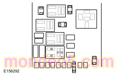
Verify
fuse 62 (50A) and 67 (50A) are OK
One Or Both High Beams Are On Continuously
Refer to Wiring Diagrams Cell 85 for schematic and connector information.
Normal Operation and Fault Conditions
REFER to:
Exterior Lighting - System Operation and Component Description
(417-01 Exterior Lighting, Description and Operation).
Fault Trigger Conditions
|
DTC
|
Description
|
Fault Trigger Conditions
|
|
B1D02:15
|
Left High Beam: Circuit Short To Battery Or Open
|
Sets when the
detects an open from the left high beam output circuit.
|
|
B1D03:15
|
Right High Beam: Circuit Short To Battery Or Open
|
Sets when the
detects an open from the right high beam output circuit.
|
Possible Sources
-
Fuse(s)
-
Wiring, terminals or connectors
-
steering column multifunction switch
-
-
Visual Inspection and Diagnostic Pre-checks
-
Inspect the
steering column multifunction switch for damage.
-
Verify
fuse 62 (50A) and 67 (50A) are OK
PINPOINT TEST D : ONE OR BOTH HIGH BEAMS ARE ON CONTINUOUSLY
| D1
CHECK HIGH BEAMS OPERATION
|
-
Place the headlamp switch in the headlamps on position.
-
Place the
steering column multifunction switch in the low beam position and observe the headlamps.
-
Observe the operation of the
and
high beam.
Are both high beams illuminated?
|
| D2
CHECK THE MULTIFUNCTION SWITCH INPUT
|
-
Using a scan tool, view
Parameter Identifications (PIDs).
-
Monitor the
Headlight Switch Mode (HEADLAMP_SW)
while placing the
steering column multifunction switch in the FLASH-TO-PASS, HIGH BEAM and LOW BEAM positions.
Do the
values agree with the
steering column multifunction switch position?
| No
|
INSTALL a new
steering column multifunction switch.
REFER to:
Steering Column Multifunction Switch LH
(211-05 Steering Wheel and Column Electrical Components, Removal and Installation).
TEST the system for normal operation. If the concern still exists, INSTALL a new
.
REFER to:
Steering Column Control Module (SCCM)
(211-05 Steering Wheel and Column Electrical Components, Removal and Installation).
|
|
| D3
CHECK HIGH BEAM VOLTAGE SUPPLY CIRCUITS FOR A SHORT TO VOLTAGE
|
-
Disconnect:
fuse 62 (50A) (
high beam).
-
Disconnect:
fuse 67 (50A) (
high beam).
Do the high beams continue to illuminate?
|
| D4
CHECK FOR CORRECT BCM (BODY CONTROL MODULE)
OPERATION
|
-
Disconnect and inspect all
connectors.
-
Repair:
-
corrosion (install new connector or terminals – clean module pins)
-
damaged or bent pins – install new terminals/pins
-
pushed-out pins – install new pins as necessary
-
Reconnect the
connectors. Make sure they seat and latch correctly.
-
Operate the system and determine if the concern is still present.
Is the concern still present?
| Yes
|
CHECK
for any applicable Technical Service Bulletins (TSBs). If a
exists for this concern, DISCONTINUE this test and FOLLOW
instructions. If no Technical Service Bulletins (TSBs) address this concern, INSTALL a new
.
REFER to:
Body Control Module (BCM)
(419-10 Multifunction Electronic Modules, Removal and Installation).
|
| No
|
The system is operating correctly at this time. The concern may have been caused by module connections. ADDRESS the root cause
of any connector or pin issues.
|
|
The Flash-To-Pass Function Is Inoperative
Normal Operation and Fault Conditions
REFER to:
Exterior Lighting - System Operation and Component Description
(417-01 Exterior Lighting, Description and Operation).
Possible Sources
Visual Inspection and Diagnostic Pre-checks
-
Inspect the
steering column multifunction switch for damage.
PINPOINT TEST E : THE FLASH-TO-PASS FUNCTION IS INOPERATIVE
| E1
CHECK THE HIGH BEAM OPERATION
|
-
Place the headlamp switch in the headlamps on position.
-
Activate and deactivate the high beams using the high beam function of the
steering column multifunction switch.
Do the high beams operate correctly?
|
| E2
CHECK THE MULTIFUNCTION SWITCH INPUT
|
-
Using a scan tool, view
Parameter Identifications (PIDs).
-
Monitor the
Headlight Switch Mode (HEADLAMP_SW)
while placing the
steering column multifunction switch in the FLASH-TO-PASS position.
Does the
value agree with the
steering column multifunction switch position?
| No
|
INSTALL a new
steering column multifunction switch.
REFER to:
Steering Column Multifunction Switch LH
(211-05 Steering Wheel and Column Electrical Components, Removal and Installation).
TEST the system for normal operation. If the concern still exists, INSTALL a new
.
REFER to:
Steering Column Control Module (SCCM)
(211-05 Steering Wheel and Column Electrical Components, Removal and Installation).
|
|
| E3
CHECK FOR CORRECT BCM (BODY CONTROL MODULE)
OPERATION
|
-
Disconnect and inspect all
connectors.
-
Repair:
-
corrosion (install new connector or terminals – clean module pins)
-
damaged or bent pins – install new terminals/pins
-
pushed-out pins – install new pins as necessary
-
Reconnect the
connectors. Make sure they seat and latch correctly.
-
Operate the system and determine if the concern is still present.
Is the concern still present?
| Yes
|
CHECK
for any applicable Technical Service Bulletins (TSBs). If a
exists for this concern, DISCONTINUE this test and FOLLOW
instructions. If no Technical Service Bulletins (TSBs) address this concern, INSTALL a new
.
REFER to:
Body Control Module (BCM)
(419-10 Multifunction Electronic Modules, Removal and Installation).
|
| No
|
The system is operating correctly at this time. The concern may have been caused by module connections. ADDRESS the root cause
of any connector or pin issues.
|
|
The Automatic High Beam Feature Is Inoperative
Normal Operation and Fault Conditions
The
controls the automatic high beam feature when active. The
turns the high beam headlamps on when the following conditions are met:
-
The feature has been enabled using the message center
-
The autolamps feature has turned the exterior lamps on
-
The fog lamps are off
-
The vehicle speed is greater than 51 km/h (32 mph)
-
The
determines the ambient lighting conditions are dark enough
-
The
does not detect any light source that can be interpreted as an illuminated vehicle lamp
The
turns the high beams off if any of the following occur:
-
The
detects any light source that can be interpreted as an illuminated vehicle lamp
-
The
determines the ambient lighting conditions are not dark enough
-
The vehicle speed falls below 44 km/h (27 mph)
-
The fog lamps are turned on
-
The autolamps are turned off
-
The
determines the view is blocked
REFER to:
Exterior Lighting - System Operation and Component Description
(417-01 Exterior Lighting, Description and Operation).
Fault Trigger Conditions
|
DTC
|
Description
|
Fault Trigger Conditions
|
|
B11C7:46
|
High Beam Sensor: Calibration / Parameter Memory Failure
|
Sets when the
detects a software problem with the calibrations.
|
|
B11C7:97
|
High Beam Sensor: Component or System Operation Obstructed or Blocked
|
Sets when the
detects a blockage in front of the high beam sensor.
|
Possible Sources
-
Windshield debris
-
(part of the interior rear view mirror)
PINPOINT TEST F : THE AUTOMATIC HIGH BEAM FEATURE IS INOPERATIVE
| NOTE:
In cold weather conditions (4°C [40°F] or less), the auto high beams are inhibited for 10 minutes to allow the camera windshield
defrost heater to clear the windshield in front of the auto high beam camera.
|
| F1
VERIFY THE HIGH BEAM HEADLAMP OPERATION
|
-
Place the headlamp switch in the headlamps on position.
-
Place the
steering column multifunction switch in the high beam position while observing the headlamps.
Do the high beam headlamps illuminate?
|
| F2
CHECK FOR IPMA (IMAGE PROCESSING MODULE A)
DIAGNOSTIC TROUBLE CODE (DTCS)
|
-
Using a scan tool, perform the
self-test.
Is
B11C7:97 present?
|
| F3
CARRY OUT THE IPMA (IMAGE PROCESSING MODULE A)
PROGRAMMABLE MODULE INSTALLATION (PMI) AND RETEST
|
-
Clear the Diagnostic Trouble Codes (DTCs). Repeat the self-test.
Is the concern still present?
| Yes
|
INSTALL a new interior rear view mirror.
REFER to:
Interior Rear View Mirror
(501-09 Rear View Mirrors, Removal and Installation).
|
| No
|
The system is operating correctly at this time.
|
|
| F4
VERIFY THAT THE AUTOMATIC HIGH BEAM SENSOR IS NOT BLOCKED
|
-
Visually verify the automatic high beam sensor is not blocked. Sources of blockage can include:
-
stickers, window decals or tags.
-
non-OEM window tinting.
Was the automatic high beam sensor blocked?
| Yes
|
If possible, REMOVE the blockage. TEST the system for normal operation. If the blockage cannot be removed, REVIEW the operation
of the automatic high beams with the customer.
|
| No
|
INSTALL a new interior rear view mirror.
REFER to:
Interior Rear View Mirror
(501-09 Rear View Mirrors, Removal and Installation).
|
|
The Daytime Running Lamps (DRL) Are Inoperative
Normal Operation and Fault Conditions
REFER to:
Exterior Lighting - System Operation and Component Description
(417-01 Exterior Lighting, Description and Operation).
Possible Sources
-
Wiring, terminals or connectors
-
PINPOINT TEST G : THE DAYTIME RUNNING LAMPS (DRL) ARE INOPERATIVE
| G1
CHECK THE OPERATION OF THE HEADLAMPS
|
-
Place the headlamp switch in the headlamps on position.
Do the low beams operate correctly?
|
| G2
CHECK FOR CORRECT BCM (BODY CONTROL MODULE)
OPERATION
|
-
Disconnect and inspect all
connectors.
-
Repair:
-
corrosion (install new connector or terminals – clean module pins)
-
damaged or bent pins – install new terminals/pins
-
pushed-out pins – install new pins as necessary
-
Reconnect the
connectors. Make sure they seat and latch correctly.
-
Operate the system and determine if the concern is still present.
Is the concern still present?
| Yes
|
CHECK
for any applicable Technical Service Bulletins (TSBs). If a
exists for this concern, DISCONTINUE this test and FOLLOW
instructions. If no Technical Service Bulletins (TSBs) address this concern, INSTALL a new
.
REFER to:
Body Control Module (BCM)
(419-10 Multifunction Electronic Modules, Removal and Installation).
|
| No
|
The system is operating correctly at this time. The concern may have been caused by module connections. ADDRESS the root cause
of any connector or pin issues.
|
|
Copyright © Ford Motor Company
 Run/Start Relay Socket Pin 3
