| 303-06D Starting System - 2.5L Duratec (125kW/170PS)
|
2013 - 2014 Fusion
|
| Diagnosis and Testing
|
Procedure revision date:
08/30/2013
|
Starting System
Inspection and Verification
Diagnostics in this manual assume a certain skill level and knowledge of Ford-specific diagnostic practices.
REFER to:
Diagnostic Methods
(100-00 General Information, Description and Operation).
-
Verify the customer concern by operating the starting system.
-
Check the battery condition and state of charge.
REFER to:
Battery
(414-01 Battery, Mounting and Cables, Diagnosis and Testing).
-
Remove the accessory drive belt.
REFER to:
Accessory Drive Belt
(303-05D Accessory Drive - 2.5L Duratec (125kW/170PS), Removal and Installation).
Verify the crankshaft and each of the components driven by the accessory drive belt rotate and are not seized or damaged.
-
If any aftermarket accessories have been added to the vehicle, make sure they are properly wired.
-
If an obvious cause for an observed or reported concern is found, correct the cause (if possible) before proceeding.
DTC Charts
Diagnostics in this manual assume a certain skill level and knowledge of Ford-specific diagnostic practices.
REFER to:
Diagnostic Methods
(100-00 General Information, Description and Operation).
PCM DTC Chart
|
DTC
|
Description
|
Action
|
|
P0512
|
Starter Request Circuit — Circuit has Power With the Ignition in the OFF Position
|
PERFORM the Ignition Switch Component Test. Refer to Wiring Diagrams Cell 149 for schematic and connector information. testing. If necessary, INSTALL a new ignition switch. If the ignition switch passed the component test, REPAIR circuit CDC35
(BU/WH) for a short to power.
|
|
P0616
|
Starter Relay "A" Circuit Low
|
GO to Pinpoint Test C
|
|
P0617
|
Starter Relay "A" Circuit High
|
GO to Pinpoint Test C
|
|
P06E9
|
Engine Starter Performance
|
If the engine cranks, Refer to Powertrain Control/Emissions Diagnosis (PC/ED) manual. If the engine does not crank,
GO to Pinpoint Test A
|
|
P0706
|
Transmission Range Sensor "A" Circuit Range/Performance
|
REFER to:
Automatic Transmission - 2.5L Duratec (125kW/170PS)
(307-01 Automatic Transmission - Vehicles With: 6-Speed Automatic Transmission - 6F35, Diagnosis and Testing).
|
|
P0707
|
Transmission Range Sensor "A" Circuit Low
|
REFER to:
Automatic Transmission - 2.5L Duratec (125kW/170PS)
(307-01 Automatic Transmission - Vehicles With: 6-Speed Automatic Transmission - 6F35, Diagnosis and Testing).
|
|
P0708
|
Transmission Range Sensor "A" Circuit High
|
REFER to:
Automatic Transmission - 2.5L Duratec (125kW/170PS)
(307-01 Automatic Transmission - Vehicles With: 6-Speed Automatic Transmission - 6F35, Diagnosis and Testing).
|
|
P1260
|
Theft Detected, Vehicle Immobilized
|
REFER to:
Electronic Engine Controls
(303-14D Electronic Engine Controls - 2.5L Duratec (125kW/170PS), Diagnosis and Testing).
|
|
P162F
|
Starter Motor Disabled - Engine Crank Time Too Long
|
Refer to Powertrain Control/Emissions Diagnosis (PC/ED) manual.
|
|
All Other DTCs
|
—
|
Refer to Powertrain Control/Emissions Diagnosis (PC/ED) manual.
|
BCM DTC Chart
Symptom Chart(s)
Symptom Chart: Starting System
Diagnostics in this manual assume a certain skill level and knowledge of Ford-specific diagnostic practices.
REFER to:
Diagnostic Methods
(100-00 General Information, Description and Operation).
Symptom Chart
|
Condition
|
Possible Sources
|
Actions
|
|
The engine does not crank
|
Refer to the Pinpoint Test.
|
GO to Pinpoint Test A
|
|
The engine cranks slowly
|
Refer to the Pinpoint Test.
|
PERFORM the starter system component test. REFER to Starter Motor - Positive Circuit Test in this section.
|
|
The engine cranks but will not start
|
-
Fuses
-
-
Fuel pump
-
Fuel pump relay
-
Starter
-
Wiring
|
Refer to Powertrain Control/Emissions Diagnosis (PC/ED) manual.
|
|
Unusual starter noise
|
Refer to the Pinpoint Test.
|
GO to Pinpoint Test B
|
|
The starter spins but the engine does not crank
|
Starter motor
|
INSPECT the starter motor mounting and engagement. REPAIR as necessary.
|
|
Damaged flexplate
|
INSPECT the flexplate for damaged, missing or worn teeth. REPAIR as necessary.
|
|
The starter does not disengage from the flexplate
|
-
Starter relay
-
Wiring, terminals or connectors
|
REMOVE the starter relay. If the engine stops cranking, INSTALL a new relay. If the engine continues to crank, REPAIR circuit
CDC35 (BU/WH) for a short to voltage.
|
Pinpoint Test(s)
Engine Does Not Crank
Refer to Wiring Diagrams Cell 20 for schematic and connector information.
Normal Operation and Fault Conditions
REFER to:
Starting System - System Operation and Component Description
(303-06D Starting System - 2.5L Duratec (125kW/170PS), Description and Operation).
DTC Fault Trigger Conditions
|
DTC
|
Description
|
Fault Trigger Conditions
|
|
P06E9
|
Engine Starter Performance
|
No engine rotation detected during crank event
|
Possible Sources
-
Battery
-
Battery cables
-
Starter motor
-
starter relay
Visual Inspection and Diagnostic Pre-checks
-
Inspect the
Run/start relay.
-
Inspect the high current
connections.
-
Verify the
fuse 84 (30A).
-
Verify the
fuse 18 (5A).
-
Inspect the Integrated Keyhead Transmitter (IKT).
PINPOINT TEST A : ENGINE DOES NOT CRANK
| NOTE:
Make sure battery voltage is greater than 12.2 volts prior to and during this pinpoint test.
|
| NOTE:
Do not have a battery charger attached during vehicle testing.
|
| A1
PERFORM INSPECTION AND VERIFICATION
|
-
Perform Inspection and Verification procedure in this section.
Was an obvious cause for an observed or reported concern found?
| Yes
|
Correct the cause as necessary.
|
|
| A2
VERIFY THE BCM (BODY CONTROL MODULE)
AND PCM (POWERTRAIN CONTROL MODULE)
PASS THE NETWORK TEST
|
-
Using a diagnostic scan tool, perform the Network Test.
Did the
and
pass the Network Test?
|
| A3
RETRIEVE DIAGNOSTIC TROUBLE CODES (DTCS)
|
-
Using a diagnostic scan tool, perform
and
self-tests.
Are any Diagnostic Trouble Codes (DTCs) present?
| Yes
|
For all
Diagnostic Trouble Codes (DTCs), REFER to the BCM DTC Chart in this section.
For
P06E9, GO to
A4
For all other
Diagnostic Trouble Codes (DTCs),
REFER to:
Electronic Engine Controls
(303-14D Electronic Engine Controls - 2.5L Duratec (125kW/170PS), Diagnosis and Testing).
|
|
| A4
CHECK BCM (BODY CONTROL MODULE)
IGN_SW_STATE PID
|
-
Using a diagnostic scan tool, view the
Parameter Identifications (PIDs).
-
Monitor the
Parameter Identification (PID) IGN_SW_STRT while turning the ignition switch from OFF to START.
Does the Parameter Identification (PID) change from Off to Start when the ignition switch is turned from OFF to START?
|
| A5
CHECK THE PCM (POWERTRAIN CONTROL MODULE)
IN GEAR-TRANSMISSION IS APPLYING A LOAD TO ENGINE (IN_GEAR) PID
|
-
Using a diagnostic scan tool, view the
Parameter Identifications (PIDs).
-
Monitor the
Parameter Identification (PID) IN_GEAR, while placing the gear selector in PARK and then NEUTRAL.
Does the Parameter Identification (PID) read No in both positions?
|
| A6
CHECK THE PCM (POWERTRAIN CONTROL MODULE)
ENGINE CRANKING (ENG_CRANK) PID
|
-
Make sure the transmission is in PARK or NEUTRAL.
-
Using a diagnostic scan tool, view the
Parameter Identifications (PIDs).
-
Monitor the
Parameter Identification (PID) ENG_CRANK while turning the ignition switch to the START position.
Does the Parameter Identification (PID) change from Inactive to Active?
|
| A7
CHECK THE STARTER RELAY CONTROL OPERATION
|
|
NOTICE:
The following step uses a test light to simulate normal circuit loads. Use only the test light recommended in the Special
Tools table at the beginning of this section. To avoid connector terminal damage, use the Flex Probe Kit for the test light
probe connection to the vehicle. Do not use the test light probe directly on any connector.
-
Remove the
starter relay.
-
Measure:
|
Positive Lead
|
Measurement / Action
|
Negative Lead
|
 starter relay pin 1
|

|
starter relay pin 2
|
-
Make sure the transmission is in PARK or NEUTRAL.
-
While holding the key in the START position, observe the test light.
Does the test light illuminate when the key is in the START position?
|
| A8
CHECK THE VOLTAGE TO THE STARTER RELAY
|
-
Measure:
|
Positive Lead
|
Measurement / Action
|
Negative Lead
|
|
BJB starter relay pin 3
|

|
Ground
|
Is the voltage greater than 11 volts?
| No
|
VERIFY the
fuse 84 (30A) is OK. If OK, REPAIR the circuit for an open. If not OK, REFER to the Wiring Diagrams manual to identify the
possible causes of the circuit short.
|
|
| A9
CHECK THE STARTER MOTOR OPERATION AT THE STARTER RELAY
|
-
With the transmission in PARK or NEUTRAL, momentarily connect a fused jumper wire:
|
Positive Lead
|
Measurement / Action
|
Negative Lead
|
|
starter relay pin 3
|

|
starter relay pin 5
|
Did the starter engage and the engine crank?
| Yes
|
INSTALL a new starter relay.
|
|
| A10
CHECK THE BATTERY GROUND CABLES
|
-
Measure:
|
Positive Lead
|
Measurement / Action
|
Negative Lead
|
|
|
Ground G108
|
|
|
|
Ground G109
|
Are the voltages greater than 11 volts?
|
| A11
CHECK THE STARTER MOTOR GROUND
|
Is the voltage greater than 11 volts?
| No
|
CLEAN the starter motor mounting flange and MAKE SURE the starter motor is correctly mounted.
|
|
| A12
CHECK THE VOLTAGE TO THE STARTER MOTOR
|
-
Measure:
|
Positive Lead
|
Measurement / Action
|
Negative Lead
|
|
C1715A-1 ("B" terminal)
|
|
Ground
|
Is the voltage greater than 11 volts?
|
| A13
CHECK THE STARTER MOTOR FOR CORRECT OPERATION
|
-
Perform Starter Motor - Positive Circuit Test in this section.
Was an obvious cause found?
| Yes
|
Correct the cause as necessary.
|
|
| A14
CHECK FOR START INPUT AT THE STARTER
|
-
Disconnect Starter solenoid C1715B
.
-
While holding the key in the START position, measure:
|
Positive Lead
|
Measurement / Action
|
Negative Lead
|
|
C1715B-1 ("S" terminal)
|
|
Ground
|
Is the voltage greater than 11 volts?
| Yes
|
CLEAN the starter solenoid "S" terminal and starter solenoid connector. CHECK the wiring and the starter motor for a loose
or intermittent connection.
|
| No
|
REPAIR the circuit for an open.
|
|
| A15
CHECK THE PCM (POWERTRAIN CONTROL MODULE)
STARTER RELAY CIRCUITS FOR A SHORT TO GROUND
|
-
Measure:
|
Positive Lead
|
Measurement / Action
|
Negative Lead
|
|
C1551B-7
|

|
Ground
|
|
C1551B-37
|
|
Ground
|
Are the resistances greater than 10,000 ohms?
| No
|
REPAIR the affected circuit.
|
|
| A16
CHECK THE PCM (POWERTRAIN CONTROL MODULE)
STARTER RELAY CIRCUITS FOR AN OPEN
|
Are the resistances less than 3 ohms?
| No
|
REPAIR the affected circuit.
|
|
| A17
CHECK FOR CORRECT PCM (POWERTRAIN CONTROL MODULE)
OPERATION
|
-
Disconnect and inspect all
connectors.
-
Repair:
-
corrosion (install new connectors or terminals - clean module pins)
-
damaged or bent pins - install new terminals/pins
-
pushed-out pins - install new pins as necessary
-
Reconnect the
connectors. Make sure they seat and latch correctly.
-
Operate the system and determine if the concern is still present.
Is the concern still present?
| Yes
|
CHECK
for any applicable Technical Service Bulletins (TSBs). If a
exists for this concern, DISCONTINUE this test and FOLLOW the
instructions. If no Technical Service Bulletins (TSBs) address this concern, INSTALL a new
.
REFER to:
Powertrain Control Module (PCM)
(303-14D Electronic Engine Controls - 2.5L Duratec (125kW/170PS), Removal and Installation).
|
| No
|
The system is operating correctly at this time. The concern may have been caused by module connections. ADDRESS the root cause
of any connector or pin issues.
|
|
Unusual Starter Noise
Normal Operation and Fault Conditions
Correct starter operation relies on correct mounting of the starter to the engine, alignment of the starter ring gear to the
flexplate and correct functioning of the starter assembly (internal gears, bearings).
Possible Sources
-
Engine
-
Starter motor
-
Starter motor mounting
Visual Inspection and Diagnostic Pre-checks
-
Inspect the starter motor.
-
Inspect the starter motor mounting.
PINPOINT TEST B : UNUSUAL STARTER NOISE
| B1
CHECK THE STARTER MOUNTING
|
-
Inspect the starter mounting bolts for looseness.
Is the starter motor mounted correctly?
| No
|
INSTALL the starter motor correctly.
REFER to:
Starter Motor
(303-06D Starting System - 2.5L Duratec (125kW/170PS), Removal and Installation).
|
|
| B2
CHECK FOR STARTER NOISE
|
-
Connect a remote starter switch between the starter solenoid C1715A-1 ("B" terminal) and C1715B-1 ("S" terminal).
-
Engage the starter and verify the noise is due to starter operation.
Is the noise due to the starter engagement?
| No
|
REFER to:
Engine
(303-00 Engine System - General Information, Diagnosis and Testing).
to continue diagnosis.
|
|
P0616 or P0617
Refer to Wiring Diagrams Cell 20 for schematic and connector information.
Normal Operation and Fault Conditions
REFER to:
Starting System - System Operation and Component Description
(303-06D Starting System - 2.5L Duratec (125kW/170PS), Description and Operation).
DTC Fault Trigger Conditions
|
DTC
|
Description
|
Fault Trigger Conditions
|
|
P0616
|
Starter Relay "A" Circuit Low
|
This
is set when the
detects a short to ground in the starter relay control circuit(s).
|
|
P0617
|
Starter Relay "A" Circuit High
|
This
is set when the
detects an open, or short to power in the starter relay control circuit(s).
|
Possible Sources
-
Wiring, terminals or connectors
-
Visual Inspection and Diagnostic Pre-checks
-
Verify the
fuse 84 (30A).
PINPOINT TEST C : P0616 OR P0617
| C1
CHECK THE PCM (POWERTRAIN CONTROL MODULE)
STARTER RELAY CIRCUITS FOR A SHORT TO VOLTAGE
|
-
Disconnect
starter relay.
-
Measure:
|
Positive Lead
|
Measurement / Action
|
Negative Lead
|
|
C1551B-7
|
|
Ground
|
|
C1551B-37
|
|
Ground
|
Is any voltage present?
| Yes
|
REPAIR the affected circuit.
|
|
| C2
CHECK THE PCM (POWERTRAIN CONTROL MODULE)
STARTER RELAY CIRCUITS FOR A SHORT TO GROUND
|
-
Measure:
|
Positive Lead
|
Measurement / Action
|
Negative Lead
|
|
C1551B-7
|
|
Ground
|
|
C1551B-37
|
|
Ground
|
Are the resistances greater than 10,000 ohms?
| No
|
REPAIR the affected circuit.
|
|
| C3
CHECK THE PCM (POWERTRAIN CONTROL MODULE)
STARTER RELAY CIRCUITS FOR AN OPEN
|
Are the resistances less than 3 ohms?
| No
|
REPAIR the affected circuit.
|
|
| C4
CHECK BJB STARTER RELAY
|
-
Replace
starter relay with a known good relay
-
Using a diagnostic scan tool, perform the
self-test.
Is
Diagnostic Trouble Code (DTC) P0616 or P0617 still present?
| No
|
INSTALL a new
starter relay.
|
|
| C5
CHECK FOR CORRECT PCM (POWERTRAIN CONTROL MODULE)
OPERATION
|
-
Disconnect and inspect all
connectors.
-
Repair:
-
corrosion (install new connectors or terminals - clean module pins)
-
damaged or bent pins - install new terminals/pins
-
pushed-out pins - install new pins as necessary
-
Reconnect the
connectors. Make sure they seat and latch correctly.
-
Operate the system and determine if the concern is still present.
Is the concern still present?
| Yes
|
CHECK
for any applicable Technical Service Bulletins (TSBs). If a
exists for this concern, DISCONTINUE this test and FOLLOW the
instructions. If no Technical Service Bulletins (TSBs) address this concern, INSTALL a new
.
REFER to:
Powertrain Control Module (PCM)
(303-14D Electronic Engine Controls - 2.5L Duratec (125kW/170PS), Removal and Installation).
|
| No
|
The system is operating correctly at this time. The concern may have been caused by module connections. ADDRESS the root cause
of any connector or pin issues.
|
|
C113A:11 or C113A:15
Refer to Wiring Diagrams Cell 23 for schematic and connector information.
Normal Operation and Fault Conditions
The wake-up control circuit wakes up the
prior to the engine cranking. The
needs to wake up prior to a crank request so it has time to go through its initialization. The wake-up control circuit is
controlled by the
. The
activates the wake-up control circuit when the driver door is opened, a key is inserted into the ignition, or when the ignition
is in the ON or START position.
DTC Fault Trigger Conditions
|
DTC
|
Description
|
Fault Trigger Conditions
|
|
C113A:11
|
Wake-up Signal: Circuit Short to Ground
|
Set by the
when a short to ground is detected on the wake-up control circuit.
|
|
C113A:15
|
Wake-up Signal: Circuit Short to Battery or Open
|
Set by the
when a short to voltage or an open is detected on the wake-up control circuit.
|
Possible Sources
-
-
-
Wiring, terminals or connectors
PINPOINT TEST D : C113A:11 OR C113A:15
| D1
CHECK FOR BCM (BODY CONTROL MODULE)
DTCS
|
-
Using a diagnostic scan tool, perform the
self-test.
Is
C113A:11 present?
| No
|
If
C113A:15 is present, GO to
D4
For all other
Diagnostic Trouble Codes (DTCs),
REFER to:
Body Control Module (BCM)
(419-10 Multifunction Electronic Modules, Diagnosis and Testing).
|
|
| D2
CHECK THE PCM (POWERTRAIN CONTROL MODULE)
FOR A SHORT TO GROUND
|
-
Using a diagnostic scan tool, clear the
Diagnostic Trouble Codes (DTCs).
-
Using a diagnostic scan tool, perform the
self-test.
Is
C113A:11 present?
|
| D3
CHECK THE PCM (POWERTRAIN CONTROL MODULE)
WAKE-UP SIGNAL CIRCUIT FOR A SHORT TO GROUND
|
-
Measure:
|
Positive Lead
|
Measurement / Action
|
Negative Lead
|
|
C1551B-35
|
|
Ground
|
Is the resistance greater than 10,000 ohms?
|
| D4
CHECK THE PCM (POWERTRAIN CONTROL MODULE)
WAKE-UP SIGNAL CIRCUIT FOR A SHORT TO VOLTAGE
|
-
Disconnect
C1551B if necessary.
-
Measure:
|
Positive Lead
|
Measurement / Action
|
Negative Lead
|
|
C1551B-35
|
|
Ground
|
Is any voltage present?
|
| D5
CHECK THE PCM (POWERTRAIN CONTROL MODULE)
WAKE-UP SIGNAL CIRCUIT FOR AN OPEN
|
-
Measure:
|
Positive Lead
|
Measurement / Action
|
Negative Lead
|
|
C1551B-35
|
|
C2280C-18
|
Is the resistance less than 3 ohms?
|
| D6
CHECK FOR CORRECT BCM (BODY CONTROL MODULE)
OPERATION
|
-
Disconnect and inspect all
connectors.
-
Repair:
-
corrosion (install new connectors or terminals - clean module pins)
-
damaged or bent pins - install new terminals/pins
-
pushed-out pins - install new pins as necessary
-
Reconnect the
connectors. Make sure they seat and latch correctly.
-
Operate the system and determine if the concern is still present.
Is the concern still present?
| Yes
|
CHECK
for any applicable Technical Service Bulletins (TSBs). If a
exists for this concern, DISCONTINUE this test and FOLLOW the
instructions. If no Technical Service Bulletins (TSBs) address this concern, INSTALL a new
.
REFER to:
Body Control Module (BCM)
(419-10 Multifunction Electronic Modules, Removal and Installation).
|
| No
|
The system is operating correctly at this time. The concern may have been caused by module connections. ADDRESS the root cause
of any connector or pin issues.
|
|
| D7
CHECK FOR CORRECT PCM (POWERTRAIN CONTROL MODULE)
OPERATION
|
-
Disconnect and inspect all
connectors.
-
Repair:
-
corrosion (install new connectors or terminals - clean module pins)
-
damaged or bent pins - install new terminals/pins
-
pushed-out pins - install new pins as necessary
-
Reconnect the
connectors. Make sure they seat and latch correctly.
-
Operate the system and determine if the concern is still present.
Is the concern still present?
| Yes
|
CHECK
for any applicable Technical Service Bulletins (TSBs). If a
exists for this concern, DISCONTINUE this test and FOLLOW the
instructions. If no Technical Service Bulletins (TSBs) address this concern, INSTALL a new
.
REFER to:
Powertrain Control Module (PCM)
(303-14D Electronic Engine Controls - 2.5L Duratec (125kW/170PS), Removal and Installation).
|
| No
|
The system is operating correctly at this time. The concern may have been caused by module connections. ADDRESS the root cause
of any connector or pin issues.
|
|
Component Test(s)
Starter Motor - Positive Circuit Test
 WARNING:
Before beginning any service procedure in this section, refer to Safety Warnings in section 100-00 General Information. Failure
to follow this instruction may result in serious personal injury.
WARNING:
Before beginning any service procedure in this section, refer to Safety Warnings in section 100-00 General Information. Failure
to follow this instruction may result in serious personal injury.
REFER to:
Health and Safety Precautions
(100-00 General Information, Description and Operation).
NOTE:
Always make the digital multimeter connection at the component terminal rather than at the wiring end of the connector. Making
a connection at the wiring end of the connector could result in false readings because the meter will not pick up a high resistance
between the wiring connector and component.
-
Make sure the battery is fully charged.
REFER to:
Battery
(414-01 Battery, Mounting and Cables, Diagnosis and Testing).
-
Perform a battery drain test.
REFER to:
Battery Drain Check
(414-01 Battery, Mounting and Cables, General Procedures).
-
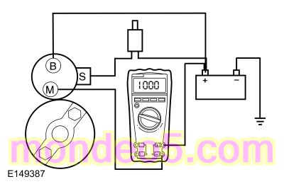
Connect a remote starter switch between starter solenoid “S” terminal and the battery positive terminal.
-
Connect the digital multimeter positive lead to the battery positive post. Connect the negative lead to the starter solenoid
"M" terminal.
-
Engage the remote starter switch. Read and record the voltage. The voltage reading should be 0.5 volt or less.
-
If the voltage reading is 0.5 volt or less, perform Starter Motor - Ground Circuit Test in this section.
-
A voltage reading greater than 0.5 volt, this is an indication of excessive resistance in the connections, the positive battery
cable or in the starter solenoid. Remove the cables from the solenoid "B", "S" and "M" terminals. Clean the cables and connections
and reinstall the cables to the correct terminals. Repeat Steps 3 through 6.
-
If the voltage reading is still greater than 0.5 volt when checked at the "M" terminal, move the digital multimeter negative
lead to the starter solenoid “B” terminal and repeat Step 5.
-
If the voltage reading at the "B" terminal is lower than 0.5 volt, the concern is in the connections at the starter solenoid
or in the solenoid contacts. Install a new starter motor.
REFER to:
Starter Motor
(303-06D Starting System - 2.5L Duratec (125kW/170PS), Removal and Installation).
-
If the voltage reading taken at the solenoid "B" terminal is greater than 0.5 volt after cleaning the cables and connections
at the solenoid, the concern is in the positive battery cable connection or in the positive battery cable itself. Clean the
positive battery cable connection. If this does not resolve the concern, install a new positive battery cable.
REFER to:
Battery Cables - 2.5L Duratec (125kW/170PS)
(414-01 Battery, Mounting and Cables, Removal and Installation).
Starter Motor - Ground Circuit Test
WARNING:
Before beginning any service procedure in this section, refer to Safety Warnings in section 100-00 General Information. Failure
to follow this instruction may result in serious personal injury.
REFER to:
Health and Safety Precautions
(100-00 General Information, Description and Operation).
A slow cranking condition can be caused by resistance in the ground or return portion of the cranking circuit. Check the
voltage drop in the ground circuit.
-
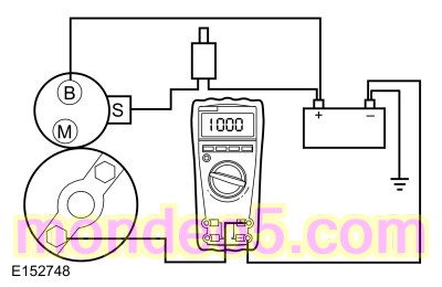
Connect a remote starter switch between starter solenoid C1715B and the battery positive terminal.
-
Connect the digital multimeter positive lead to the starter motor housing (the connection must be clean and free of rust or
grease). Connect the negative lead to the negative battery terminal.
-
Engage the remote starter switch and crank the engine. Read and record the voltage reading. The reading should be 0.5 volt
or less.
-
If the voltage reading is greater than 0.5 volt, clean the negative cable connections at the battery, the body ground connections
and the starter ground connection. Retest.
-
If the voltage reading is greater than 0.5 volt, install a new negative battery cable.
REFER to:
Battery Cables - 2.5L Duratec (125kW/170PS)
(414-01 Battery, Mounting and Cables, Removal and Installation).
-
If the voltage reading is less than 0.5 volt and the engine still cranks slowly, install a new starter motor.
REFER to:
Starter Motor
(303-06D Starting System - 2.5L Duratec (125kW/170PS), Removal and Installation).
Copyright © Ford Motor Company
 Starter motor case