 WARNING:
Before beginning any service procedure in this section, refer to Safety Warnings in section 100-00 General Information. Failure
to follow this instruction may result in serious personal injury.
WARNING:
Before beginning any service procedure in this section, refer to Safety Warnings in section 100-00 General Information. Failure
to follow this instruction may result in serious personal injury.
| 206-07 Power Brake Actuation | 2013 - 2014 Fusion |
| Removal and Installation | Procedure revision date: 03/11/2013 |
Removal
NOTICE: Do not spill brake fluid on painted or plastic surfaces or damage to the surface may occur. If brake fluid is spilled onto a painted or plastic surface, immediately wash the surface with water.
NOTE: Removal steps in this procedure may contain installation details..
WARNING:
Before beginning any service procedure in this section, refer to Safety Warnings in section 100-00 General Information. Failure
to follow this instruction may result in serious personal injury.

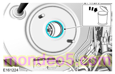
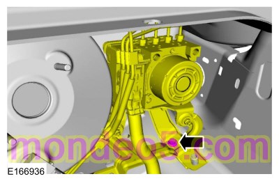
NOTICE: Before removing the master cylinder, relieve the vacuum in the brake booster or the master cylinder O-ring seal may be drawn into the brake booster, causing brake booster failure and increased brake pedal effort.
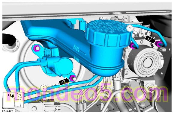
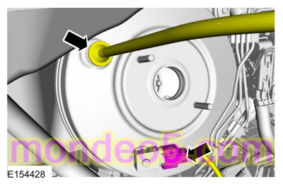
NOTE: Make sure that the master cylinder-to-booster seal is removed with the master cylinder.
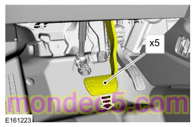
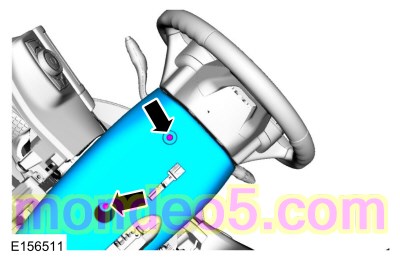
NOTICE: Do not service the brake pedal or brake booster without first removing the stoplamp switch. This switch must be removed with the brake pedal in the at-rest position. The switch plunger must be compressed for the switch to rotate in the bracket. Attempting to remove the switch when the plunger is extended (during pedal apply) will result in damage to the switch.
Refer to: Stoplamp Switch (417-01 Exterior Lighting, Removal and Installation).

Installation
Copyright © Ford Motor Company