| 414-05 Voltage Converter/Inverter
|
2013 - 2014 Fusion
|
| Diagnosis and Testing
|
Procedure revision date:
01/4/2013
|
Direct Current/Alternating Current (DC/AC) Inverter
DTC and Symptom Chart
Body Control Module DTC Chart
|
DTC
|
Description
|
Action
|
|
B1330:01
|
DC/AC Inverter Module: General Electrical Failure
|
GO to Pinpoint Test A
|
|
B1330:02
|
DC/AC Inverter Module: General Signal Failure
|
GO to Pinpoint Test C
|
|
B1330:08
|
DC/AC Inverter Module: Bus Signal / Message Failure
|
GO to Pinpoint Test C
|
|
B1330:49
|
DC/AC Inverter Module: Internal Electronic Failure
|
CLEAR the
. REPEAT the self-test. If
B1330:49 is retrieved again, INSTALL a new Direct Current/Alternating Current (DC/AC) Inverter.
REFER to:
Direct Current/Alternating Current (DC/AC) Inverter
(414-05 Voltage Converter/Inverter, Removal and Installation).
|
|
B1330:55
|
DC/AC Inverter Module: Not Configured
|
CLEAR the
. REPEAT the self-test. If
B1330:55 is retrieved again, INSTALL a new Direct Current/Alternating Current (DC/AC) Inverter.
REFER to:
Direct Current/Alternating Current (DC/AC) Inverter
(414-05 Voltage Converter/Inverter, Removal and Installation).
|
|
B1330:9A
|
DC/AC Inverter Module: Component or System Operating Conditions
|
ADDRESS all other DTCs first. If no other DTC's are present ADDRESS any symptoms. REFER to SYMPTOM CHART in this section.
If no symptoms are present clear the
. If DTC returns and no symptoms are present INSTALL a new Direct Current/Alternating Current (DC/AC) Inverter.
REFER to:
Direct Current/Alternating Current (DC/AC) Inverter
(414-05 Voltage Converter/Inverter, Removal and Installation).
|
| Symptom
|
Possible Sources
|
Action
|
- No power at the
power point or the
power point
indicator flashes with the key in the ON position.
|
- Refer to the Pinpoint Test
|
- DISCONNECT all electrical accessories from the
oulet and VERIFY that cabin temperature is below 75°C (167°F). CYCLE the ignition. TEST the system for normal operation.
If the system is operating normally, RETURN the vehicle to the customer. If the
outlet
indicator is still flashing,
GO to Pinpoint Test A
|
- The
/
inverter does not operate correctly — the
power point
indicator is never on
|
- Refer to the Pinpoint Test
|
|
- The
power point turns off after 13 minutes
|
- Refer to the Pinpoint Test
|
|
Pinpoint Tests
Diagnostics in this manual assume a certain skill level and knowledge of Ford-specific diagnostic practices.
REFER to:
Diagnostic Methods
(100-00 General Information, Description and Operation).
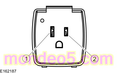
No Power at the
Power Point or the
Power Point
Indicator Flashes with the Key in the ON Position
Refer to Wiring Diagrams Cell 44 for schematic and connector information.
Normal Operation and Fault Conditions
The
/
inverter receives 12 volts
on two circuits and is grounded by another circuit. The incoming
voltage is internally converted to 60 Hz 110 volts
voltage that is output to the
power point.
NOTE:
The electrical device that is powered by the
power point must not exceed 150 watts.
NOTE:
If the green
is flashing, the
power point may be overloaded, overheated or shorted. Unplug the electrical device from the
power point and cycle the ignition. Refer to the Owner's Literature to determine if the electrical device is appropriate
for the
power point.
Diagnostic Trouble Code (DTC) Fault Trigger Conditions
|
DTC
|
Description
|
Fault Trigger Conditions
|
|
B1330:01
|
DC/AC Inverter Module: General Electrical Failure
|
Sets in the
when the general electrical fault is detected by the
/
inverter.
|
Possible Sources
-
Fuse(s)
-
Wiring, terminals or connectors
-
/
inverter
-
power point
Visual Inspection and Diagnostic Pre-checks
-
Verify that any device being used in the
outlet is rated at less than 150 watts
-
Verify the
outlet is not being used with the engine off for a period longer than 13 minutes without starting the engine or cycling the
ignition
-
Verify the cabin temperature is less than 75ºC (167ºF)
-
Verify the
fuse 23 (10A) is OK.
-
Verify the
fuse 81 (40A) is OK.
-
Inspect the
outlet for damage.
Diagnostics in this manual assume a certain skill level and knowledge of Ford-specific diagnostic practices.
REFER to:
Diagnostic Methods
(100-00 General Information, Description and Operation).
The
/
Inverter Does Not Operate Correctly — The
Power Point
Indicator is Never On
Refer to Wiring Diagrams Cell 44 for schematic and connector information.
Normal Operation and Fault Conditions
The
/
inverter receives 12 volts
on two circuits and is grounded by another circuit. The incoming
voltage is internally converted to 60 Hz 110 volts
voltage that is output to the
power point. If a fault in the system is detected, the
flashes when the key is in the ON position. The
continuously illuminates if the system is operating correctly when the key is in the ON position. The
/
inverter supplies 12V
and a ground to the
.
Possible Sources
-
Fuse(s)
-
Wiring, terminals or connectors
-
/
inverter
-
power point
Visual Inspection and Diagnostic Pre-checks
-
Verify the
fuse 23 (10A) is OK.
-
Verify the
fuse 81 (40A) is OK.
-
Inspect the
outlet for damage.
Diagnostics in this manual assume a certain skill level and knowledge of Ford-specific diagnostic practices.
REFER to:
Diagnostic Methods
(100-00 General Information, Description and Operation).
The
Power Point Turns Off After 13 Minutes
Refer to Wiring Diagrams Cell 44 for schematic and connector information.
Normal Operation and Fault Conditions
The
/
inverter receives a signal from the
over the
whenever the engine is running. If the
/
inverter does not receive this message for 13 minutes, the inverter stops supplying 110 volts to the power outlet and the
green
indicator flashes. The system can be reset by cycling the ignition from ON to OFF and back to ON, however the system only
operates for another 13 minutes unless the signal is received from the
that the engine is running.
Diagnostic Trouble Code (DTC) Fault Trigger Conditions
|
DTC
|
Description
|
Fault Trigger Conditions
|
|
B1330:02
|
DC/AC Inverter Module: General Signal Failure
|
Sets in the
when sets when a general signal failure occurs on the LIN.
|
|
B1330:08
|
DC/AC Inverter Module: Bus Signal / Message Failure
|
Sets in the
when there is a LIN communication fault from the
/
inverter.
|
Possible Sources
-
Wiring, terminals or connectors
-
/
inverter
-
Visual Inspection and Diagnostic Pre-checks
-
Verify the concern by monitoring the
outlet
indicator for 13 minutes with the engine running. If the
indicator starts to flash after 13 minutes, continue to the pinpoint test. If the system continues to operate normally after
13 minutes, make sure the customer is aware of the
/
inverter time-out function.
PINPOINT TEST C : THE AC (ALTERNATING CURRENT)
POWER POINT TURNS OFF AFTER 13 MINUTES
| NOTICE:
Use the correct probe adapter(s) from the Flex Probe Kit when taking measurements. Failure to use the correct probe adapter(s)
may damage the connector.
|
| C1
RETRIEVE BCM (BODY CONTROL MODULE)
DTCS
|
-
Using a scan tool, perform
self-test.
Is
U0100:00, B1330:02, or B1330:08 present?
| Yes
|
If
U0100:00 is present
REFER to:
Body Control Module (BCM)
(419-10 Multifunction Electronic Modules, Diagnosis and Testing).
For DTCs B1330:02 or B1330:08 GO to
C2
|
|
| C2
CHECK THE LIN (LOCAL INTERCONNECT NETWORK)
COMMUNICATION CIRCUIT FOR A SHORT TO VOLTAGE
|
-
Disconnect
/
Inverter C3501
.
-
Measure:
|
Positive Lead
|
Measurement / Action
|
Negative Lead
|
|
C3501-9
|

|
Ground
|
Is any voltage present?
|
| C3
CHECK THE LIN (LOCAL INTERCONNECT NETWORK)
COMMUNICATION CIRCUIT FOR A SHORT TO GROUND
|
-
Measure:
|
Positive Lead
|
Measurement / Action
|
Negative Lead
|
|
C3501-9
|
|
Ground
|
Is the resistance greater than 10,000 ohms?
|
| C4
CHECK THE LIN (LOCAL INTERCONNECT NETWORK)
COMMUNICATION CIRCUIT FOR AN OPEN
|
-
Measure:
|
Positive Lead
|
Measurement / Action
|
Negative Lead
|
|
C3501-9
|
|
C2280G-52
|
Is the resistance less than 3 ohms?
| Yes
|
INSTALL a new
/
inverter.
REFER to:
Direct Current/Alternating Current (DC/AC) Inverter
(414-05 Voltage Converter/Inverter, Removal and Installation).
TEST the system for normal operation. If the
outlet still turns off after 13 minutes when the engine is running, INSTALL a new
.
REFER to:
Body Control Module (BCM)
(419-10 Multifunction Electronic Modules, Removal and Installation).
|
|
Copyright © Ford Motor Company

 pin 1 (component side)
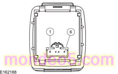 pin 6 (component side)
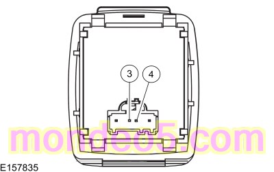 pin 3 (component side)