| 413-06 Horn | 2013 - 2014 Fusion |
| Description and Operation | Procedure revision date: 08/1/2012 |
System Operation
System Diagram
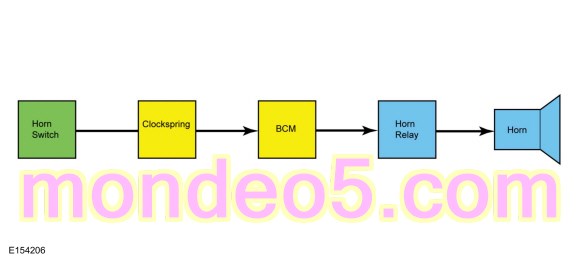
Horn Operation
The horn switch consists of 2 sets of contacts separated by springs. The lower set is connected to ground and the upper set is connected to the horn signal circuit. When the driver airbag is pressed, it pushes down on the upper set of contacts, collapsing the springs and allowing the contacts to touch. When the contacts touch, it completes the circuit and provides the ground signal, which is routed through the clockspring to the BCM . The BCM grounds the horn relay coil to energize the relay. When energized, the horn relay provides voltage to the horn, enabling the horn to sound.
Copyright © Ford Motor Company