| 415-00B Information and Entertainment System - General Information - Vehicles With: AM/FM/CD/SYNC/Touchscreen Display | 2013 - 2014 Fusion |
| Description and Operation | Procedure revision date: 05/22/2013 |
System Operation
Information and Entertainment System
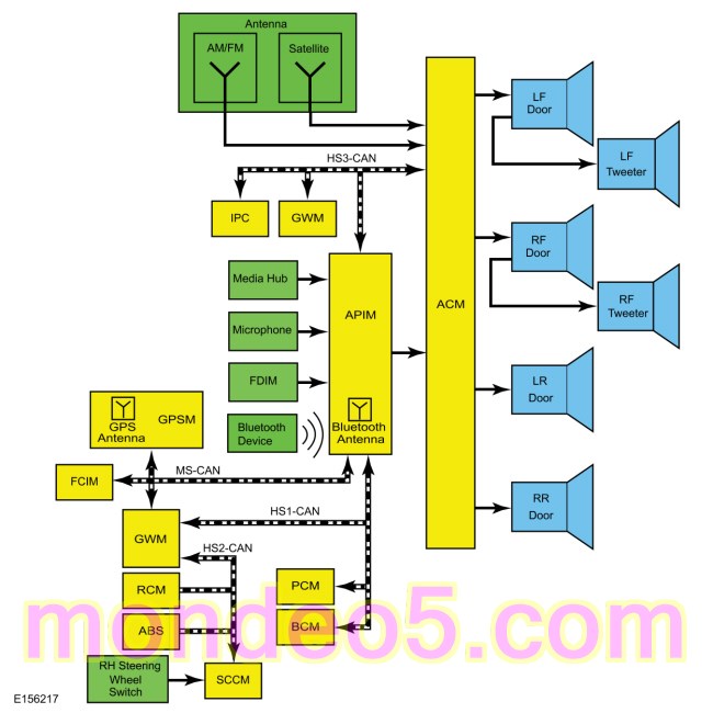
System Diagram — Without Active Noise Control
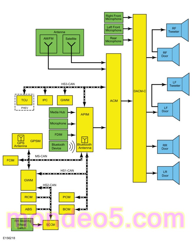
System Diagram — With Active Noise Control
Network Message Chart
ACM Network Input Messages
| Broadcast Message | Originating Module | Message Purpose |
|---|---|---|
| Audio settings | IPC | Customer audio settings that are set in the IPC . |
| Battery low state of charge | BCM | Used to shut down the audio system if the battery state of charge is below predetermined level. |
| Belt-Minder® audio mute | IPC | When this signal is active, the speaker output is muted to allow the Belt-Minder® tone to be more easily heard. This message only applies to vehicles with MyKey® enabled. |
| Day/night status | BCM | Used for day/night illumination status for the audio system. |
| FCIM button state | FCIM | Indicates when a button is pressed on the FCIM so the audio system can make the desired setting change. Ignition status BCM indicates when a button is pressed on the FCIM so the audio system can make the desired setting change. |
| Ignition status | BCM | Ignition RUN, START and ACCESSORY states required for the ACM operating modes and fault reporting. |
| MyKey® volume limit status | IPC | Used by the ACM to limit the audio system volume when a MyKey® restricted key is in use. |
| Vehicle configuration data | BCM | Used to verify vehicle configuration data such as VIN and system module configuration. |
| Steering wheel switch data | SCCM | Used for the 3 RH 2-way steering wheel switch input signals to control the redundant audio system functions. |
| Vehicle speed | PCM | Vehicle speed data used for speed compensated volume function. |
APIM Network Input Messages
| Broadcast Message | Originating Module | Message Purpose |
|---|---|---|
| Airbag deployment status | RCM | This message indicates air bag deployment has occurred. |
| Audio settings | IPC | Customer audio settings that are set in the IPC . |
| ACM track information | ACM | ACM sends track information to be displayed on the FDIM . |
| Audio volume status | FCIM | Volume request from the FCIM . |
| Battery/charge status | GWM | Used for the display of the battery and charging system. |
| DSP chime request | Audio DSP Module | Indicates when a chime request has been requested. |
| Day/night status | BCM | Used for day/night illumination status for the FDIM . |
| eCall notification | RCM | This message indicates eCall notification is being initiated due to air bag deployment. |
| Energy consumption display units | IPC | Used for the energy display. |
| FCIM bezel diagnostic status | GWM | Indicates the audio system has been put into diagnostic mode. |
| FCIM button state | FCIM | Indicates when a button is pressed on the FCIM so the audio system can make the desired setting change. |
| Gear lever position | GWM | Indicates the gear lever position so the APIM can make the desired setting change. |
| GPS compass direction | GPSM | Used by the turn-by-turn navigation. |
| GPS data | GPSM | Used for vehicle positioning, heading and direction to the APIM for navigation. |
| Ignition status | BCM | Ignition RUN, START and ACCESSORY states required for the APIM operating modes and fault reporting. |
| Language update status | IPC | Indicates the selected language so the APIM can make the desired setting change. |
| Life cycle mode | GWM | Used for the display of the battery and charging system. |
| Load shed level | IPC | This message is for requesting the APIM to enter battery load shed mode and displays a message on the FDIM . |
| MyKey volume limit status | IPC | Used by the APIM to limit the audio system volume when a MyKey® restricted key is in use. |
| Navigation rolling wheel count and direction | ABS module | This message provides for more accurate tracking of the vehicle position when the GPS signal is temporarily unavailable for gear lever position for vehicle direction data for navigation. |
| Parklamp status | GWM | Used for the screen brightness of the FDIM . |
| Regenerated energy display | GWM | Used for the display of the battery and charging system. |
| Remote start status | GWM | Used to display the remote start status. |
| Satellite radio mode | ACM | Used to display the satellite radio modes and functions. |
| Satellite radio status | ACM | Used to display the satellite radio modes and functions. |
| Satellite radio error status | ACM | Used for the satellite radio error status. |
| Setpoint volume | FCIM | Used for volume adjustment setpoint from the FCIM to the FDIM . |
| Set volume | FCIM | Used for set volume from the FCIM to the FDIM . |
| Steering wheel switch data | SCCM | Used for the RH steering wheel switch input signals to operate the IPC infotainment display and SYNC® functionality. |
| Telematic activation request | TCU | Used to activate the telematics request. |
| Vehicle configuration data | BCM | Used to verify vehicle configuration data such as VIN and system module configuration. |
| Vehicle speed | PCM | Vehicle speed data used for navigation functionality. |
| Vehicle trip summary display | IPC | Used to display the trip summary. |
DACMC Network Input Messages
| Broadcast Message | Originating Module | Message Purpose |
|---|---|---|
| Accelerator pedal position | PCM | Used for throttle position status for the active noise control system. |
| Accessory delay status | PCM | Used for accessory delay status for the active noise control system. |
| Drivers door ajar status | BCM | Used for drivers door ajar status for the active noise control system. |
| Engine RPM | PCM | Engine speed data used for the active noise control system. |
| Hood ajar status | BCM | Used for hood ajar status for the active noise control system. |
| Left rear door ajar status | BCM | Used for left rear door ajar status for the active noise control system. |
| Luggage compartment lid ajar status | BCM | Used for luggage compartment lid status for the active noise control system. |
| Multimedia system ON/OFF | IPC | Used for audio system ON/OFF status for the active noise control system. |
| Multimedia system fault reporting status | BCM | Used for reporting fault status of audio system to the DACMC . |
| Passengers door ajar status | BCM | Used for passenger door ajar status for the active noise control system. |
| Passengers rear door ajar status | BCM | Used for passenger rear door ajar status for the active noise control system. |
| Gear lever position | PCM | Used to verify the gear lever position for the active noise control system. |
FCIM Network Input Messages
| Broadcast Message | Originating Module | Message Purpose |
|---|---|---|
| Audio system response status | GWM | Used button illumination in the FCIM . |
| Day/night status | BCM | Used for day/night illumination status for the FCIM . |
| Ignition status | BCM | Ignition RUN, START and ACCESSORY states required for the FCIM operating modes and fault reporting. |
| Illumination dimming level | BCM | Controls the backlight intensity, based on the input from the dimmer switch. |
| Vehicle configuration data | BCM | Used to verify vehicle configuration data such as VIN and system module configuration. |
GPSM Network Input Messages
| Broadcast Message | Originating Module | Message Purpose |
|---|---|---|
| Ignition status | BCM | Ignition RUN, START and ACCESSORY states required for the GPSM operating modes and fault reporting. |
| Gear lever position | BCM | Used to verify the selector lever status for navigation. |
| Navigation rolling wheel count and direction | ABS module | Used to verify the gear lever position for vehicle direction data for navigation. |
| Vehicle yaw rate | ABS module | Used to verify the vehicle acceleration data for navigation. |
| Vehicle configuration data | BCM | Used to verify vehicle configuration data such as VIN and system module configuration. |
IPC Network Input Messages
| Broadcast Message | Originating Module | Message Purpose |
|---|---|---|
| ACM track information | ACM | Used to display track information from the ACM . |
| DSP chime request | Audio DSP Module | Indicates when a chime request has been requested. |
| Multimedia player total play time status | APIM | Used to display track information from the ACM . |
| Vehicle configuration data | BCM | Used to verify vehicle configuration data such as VIN and system module configuration. |
TCU Network Input Messages - PHEV
| Broadcast Message | Originating Module | Message Purpose |
|---|---|---|
| Ambient interior temperature | FCIM | Used to verify vehicle interior temperature for conditioning and to send alerts when vehicle has reached preset temperature. |
| Battery state of charge data | GWM | Used to verify the battery state of charge and to send alerts when vehicle has reached preset charge level, has the ability to reach a particular destination, is not charging when scheduled, or when charging stops unexpectedly. |
| Charge port status | GWM | Used to verify if a device is plugged into the charge inlet port. Indicates fault state if it is unknown if a device is plugged in. |
| Charging power type | GWM | Used to verify the type of outlet the charger is plugged into (120V or 240V). |
| Door status | BCM | Used to verify door latch and lock position. |
| GPS data | GPSM | Used for on-board navigation route planning and to indicate vehicle location. |
| Ignition status | BCM | OFF, ACCESSORY, RUN, and START ignition states required for TCU operating modes and fault reporting. |
| Remote start status | BCM | Used to indicate a remote start interruption or failure. |
| Vehicle configuration data | BCM | Used to verify vehicle configuration data such as the VIN and system module configuration. |
| Vehicle speed | PCM | Used to disable certain MyFord® Mobile features when the vehicle is in motion. |
Accessory Delay Feature
The accessory delay feature allows the audio system to be operated for a preset period of time after the ignition is turned off and a front door has not been opened.
Active Noise Control
The active noise control is an audio system feature that minimizes or cancels certain low frequency engine noises within the passenger compartment. The active noise control system is integral to the audio system utilizing 3 microphones, the DACMC and the input audio signals from the ACM .
The DACMC is a digital signal processor that consists of an internal analog/digital converter and tone generator.
While the engine is running, the microphones, located in the headliner (two in the front and one in the rear), monitor the engine noise resonating in the passenger compartment. The analog signals from the microphones are processed through the analog/digital converter integral to the DACMC . The DACMC receives the vehicles engine speed from the PCM and determines the frequency to be canceled from the engine speed data and microphones input signals. The DACMC produces an opposing output frequency signal from the internal tone generator. The DACMC mixes the opposing output frequency signal and audio signals that are from the ACM . The amplified mixed audio signal are sent to the door speakers eliminating some of the low frequency engine noise.
AM / FM Radio
The AM / FM antenna receives AM and FM radio waves. The antenna module sends the radio waves to the ACM through the AM / FM antenna cable. The ACM powers the AM / FM antenna to amplify the AM signal.
For vehicles without active noise control, the ACM converts the radio waves to a fluctuating AC output voltage to the system speakers.
For vehicles with active noise control, the ACM converts the radio waves to a fluctuating AC output voltage to the DACMC . Three noise cancellation microphones, located in the vehicle, measure the amplitude and phase of the engine noise and sends it to the DACMC . The DACMC receives engine speed data and calculates the targeted frequency that needs to be cancelled. The DACMC outputs the engine noise cancellation frequency and fluctuating AC output voltage to the system speakers.
APIM Programming
The APIM for this vehicle requires specific programming procedures for correct operation. APIM programming is required when:
There are 3 types of APIM programming available:
There are 3 types of software installation methods available depending on the type of programming selected:
NOTE: Vehicle Interface Processor (VIP) programming is not selectable because the Vehicle Interface Processor (VIP) is configured automatically during programming.
There are some general programming guidelines that are applicable to multiple types of programming:
To perform module replacement programming,
Refer to:
SYNC Module [APIM] Replacement Programming
(415-00B Information and Entertainment System - General Information - Vehicles With: AM/FM/CD/SYNC/Touchscreen Display, General Procedures).
To perform standard programming,
Refer to:
SYNC Module [APIM] Standard Programming
(415-00B Information and Entertainment System - General Information - Vehicles With: AM/FM/CD/SYNC/Touchscreen Display, General Procedures).
To perform custom programming,
Refer to:
SYNC Module [APIM] Custom Programming
(415-00B Information and Entertainment System - General Information - Vehicles With: AM/FM/CD/SYNC/Touchscreen Display, General Procedures).
Audio Extended Play Mode
The audio extended play mode is a feature that enables the audio system after the ignition is off and any door has been opened. When the power button on the FCIM is pressed, the audio system functionality is restored and remains active for a period of 20-60 minutes, depending on configuration settings. To turn the audio system off, the power button on the FCIM is pressed. The audio extended play mode will be disabled if the battery saver function is enabled.
Audible Prompts
The APIM receives stereo inputs from connected mobile phones and mono inputs from the SYNC® microphone.
Stereo and mono inputs, voice prompts, the Text-To-Speech (TTS) feature, ringtones, and any audio received through a connected mobile phone are transmitted to the ACM as stereo or mono sound.
The Text-To-Speech (TTS) feature speaks information so that it does not have to be read from the display.
Battery Load Shed
The BCM uses the battery current sensor to keep track of the battery state of charge. The battery current sensor is a Hall-effect sensor attached to the battery ground cable. When the engine is off, and the BCM determines the battery state of charge is below 40% or 10% of the charge has been drained or 45 minutes have elapsed, a load shed message is sent over the CAN . This message turns off the audio/navigation system to save the remaining battery charge. Under this condition, SYS OFF TO SAVE BATT is displayed on the centerstack infotainment display to notify the driver that battery protection actions are active.
Engine off load shed occurs when the engine is not running, and the ignition is in the ACC or RUN position. To clear the load shed state, restart the engine.
Bluetooth Mode
Bluetooth is a secure, short-range radio frequency that allows devices to communicate wirelessly through radio waves. The operating range of a Bluetooth signal is a maximum of 9.75 m (32 ft).
The Bluetooth interface can accommodate both Bluetooth-enabled mobile phones and Bluetooth-enabled media devices. The SYNC® system allows interaction with several types of customer Bluetooth devices, including mobile phones and media devices. The APIM contains an on-board Bluetooth chipset, which enables certain wireless devices to interact with the system. Any Bluetooth device used with the SYNC® system must first be paired with the system before it is operational.
Only one Bluetooth phone and one Bluetooth media device can be connected to the system at any one time. If an additional device of either type is paired with the system and made active, the APIM disconnects any active connection and establishes a connection with the new device.
When a new Bluetooth device is added, the APIM and the Bluetooth device must be paired together. Most Bluetooth devices can pair with the SYNC® system, although functionality may vary. To determine if a Bluetooth device is supported, verify the customer device is on the compatibility list for the current APIM software level.
Pairing a Bluetooth device is accomplished through the "Add Device" selection of the phone menu. When pairing a device, the SYNC® system generates a unique PIN that must be entered on the Bluetooth device in order for the pairing process to be successful. There are also some device-specific actions that must take place. For additional information on the pairing process, refer to the Owner's Literature.
It is important to understand that not all mobile phones have the same level of features when interacting with the SYNC® system. For a list of compatible phones, refer to the SYNC® MyRide website.
Composite Audio-Video Input Mode
The composite audio and video inputs consist of the RCA jack connections that are used for playing video or audio content from an external device (such as a gaming system). The media hub contains an internal composite audio/video translator connected to the external RCA jacks, which output video and audio signals to the APIM via a shielded audio and video harness.
MyFord® Mobile - PHEV
The MyFord® Mobile system uses the TCU to provide remote connectivity through the MyFord® Mobile website and mobile phone application to monitor and perform key vehicle functions such as:
MyKey® Audio Operation
When a MyKey® is in use:
The MyKey® also has an optional setting that limits the audio system volume. The maximum volume of the audio system is limited to 45%. In an attempt to exceed the limited volume, the MyKey® VOLUME LIMITED message is displayed in the centerstack infotainment display. The speed compensated volume feature will be disabled.
Refer to the Owner's Literature for information on MyKey®.
Navigation
The navigation system guides the user to a pre-entered destination. Map data is read from the map data SD card plugged into the media hub. The APIM calculates route information based on GPS data received by the GPSM . The APIM also uses vehicle speed and transmission gear selected signals received through the network to detect vehicle speed and direction, resulting in more accurate navigation tracking. The navigation display is shown on the FDIM .
The compass heading is derived from the GPS antenna signal. There are no serviceable parts for the compass.
The voice recognition system allows the user to interface with the system without using the touchscreen. A microphone located in the headliner provides a direct input to the APIM .
Satellite Radio
The satellite antenna receives digital signals and sends them to the ACM through the satellite radio antenna cable. The satellite radio receiver is built into the ACM .
SD Card Audio Mode
The SD card slot can be used for playing audio content that is stored on the SD card.
SD Card Video Mode
The SD card slot has the capability to view photos stored on memory SD cards and display them on the FDIM .
SIRIUS® Data Services
The satellite radio system has SIRIUS® data services that are separate subscription services which are received through the satellite receiver. The data services include periodic updates for:
Some services may be available separately while others are only available as packages.
Speed Compensated Volume
The ACM adjusts the audio system volume based on the VSS signal to compensate for speed and wind noise.
Steering Wheel Switch Function
The RH steering wheel switch consists of an integrated 5-way upper switch and three 2-way toggle lower switches. The 5-way steering wheel switch operates the IPC infotainment display. The three 2-way toggle steering wheel switches operate the audio system functions including SYNC®.
SYNC® System
The SYNC® system is a hands-free communication and entertainment system that supports many features. All features are not available with every phone.
The SYNC® system provides the ability to:
SYNC® Traffic, Directions and Information
The SYNC® traffic, directions and information service is a subscription-based service that includes precise turn-by-turn directions, personalized real-time traffic updates with text alerts, business search, entertainment, news, sports, stocks, travel and weather. The customers mobile phone is used to access and download the SYNC® services. The GPS antenna, that is integral to the GPSM , is used to detect the location and direction of the vehicle. For traffic, directions and information services subscription, refer to the SYNC® MyRide website.
USB Audio Mode
The USB port can be used for connecting a media device (such as an iPod®) with the device's available cable, or for directly plugging in a portable mass storage device, such as a thumb drive. When playing media files stored on a mass storage device, the SYNC® system only plays files that do not have Digital Rights Management (DRM) protection. The USB port can also be used for uploading vehicle Application upgrades. The USB port is powered by the APIM , so no external power source is needed to power a device plugged into the USB port if the device supports this feature.
In addition to audio information, metadata (information such as artist, album title, song title, and genre) may also be sent to the APIM from a device plugged into the USB port. The APIM uses the metadata to create indexes that can be used to sort for particular music, based on customer preference. Not all USB devices can send metadata to the APIM . When a new media device is connected to the SYNC® system, the APIM automatically indexes the information. This may take several minutes (depending on the amount of data on the device), and is considered normal operation. When a device that was previously connected to the SYNC® system is reconnected, the APIM updates the index (rather than creating a new one), which reduces the amount of time needed to index the device.
Image files can be saved to the APIM from a USB device. These images can be displayed on the FDIM as wallpaper backgrounds.
Voice Recognition
Voice recognition is used for many vehicle functions including the audio system. The microphone relays the microphone input to the APIM through dedicated wiring. The TTS and voice prompt features speak certain text information and interaction requests to minimize driver distraction by having to look at the audio system display while driving. The ringtone alerts the driver to an incoming call. The microphone is also used to detect outgoing audio during a phone call.
Audible prompts can range from a simple tone to more elaborate spoken text, based on the customer setting. When interaction mode is set to standard, detailed guidance is provided. When interaction mode is set to advanced, most prompts are tones only and minimal audible guidance is provided. Refer to the Owner's Literature for information on voice interaction.
The audio signals for the TTS and voice prompt features, the ringtones, and audio from the outside device during a phone call, are sent from the APIM to the ACM .
Component Description
ACM
The ACM can be operated with the ignition in RUN or ACC. The accessory delay feature allows the audio system to be operated for a preset period of time after the ignition is turned off and a front door has not been opened. The ACM requires Programmable Module Installation (PMI) when it is replaced.
For vehicles without noise cancellation, the ACM provides the audio signals to the subwoofer amplifier and all speakers.
For vehicles with noise cancellation ACM provides the audio signals to the subwoofer amplifier, the instrument panel speaker and the DACMC . The DACMC processes the audio signals with the noise cancellation signals and provides the door speakers with the amplified audio signals.
Antenna
The AM / FM antenna has an integrated antenna module that is powered by the ACM to improve AM / FM reception. If the vehicle is equipped with satellite radio, the satellite antenna is integrated into the roof-mounted antenna module.
APIM
The APIM consists of 2 internal modules: the Customer Interface Processor (CIP) and the Vehicle Interface Processor (VIP). These modules are not replaceable individually, but can be flashed independently, if required.
The Customer Interface Processor (CIP) interfaces with all of the inputs to the APIM . It contains an analog-to-digital-to analog converter, as well as the Bluetooth chipset. Any application upgrades that are available to the consumer are loaded directly to the Customer Interface Processor (CIP) through the USB port.
The Vehicle Interface Processor (VIP) provides an interface between the Customer Interface Processor (CIP) and the vehicle. Its main functions are controlling the APIM power management and translating both inbound and outbound signals. In addition, the Vehicle Interface Processor (VIP) queries the modules on the network to retrieve any Diagnostic Trouble Codes (DTCs) when a vehicle health report is requested.
DACMC
The DACMC is a digital signal processor that consists of an internal analog/digital converter, amplifier, and tone generator.
The DACMC operates with the ignition in RUN, ACC, or OFF. Active noise control functions only operate with the ignition in RUN.
The ACM outputs voltage through the enable circuit to enable the DACMC amplifier. The ACM also uses this circuit to detect an amplifier overload condition. In the event of an amplifier overload, the DACMC modifies the voltage signal from the ACM to increase the voltage on the enable circuit to a higher level than provided by the ACM . This higher voltage level causes the ACM to momentarily reduce the audio levels on the left and right audio output channels to the DACMC to prevent clipping and speaker damage.
The DACMC receives engine rotation speed data and active noise control microphone input signals and calculates the targeted frequency needed to cancel engine noise within the passenger compartment. The DACMC outputs the engine noise cancellation frequency to all audio system speakers, except the instrument panel center speaker (if equipped), as fluctuating AC voltage.
The DACMC receives audio signals from the ACM when audio is being played. The DACMC amplifies these signals and sends them to the door speakers as fluctuating AC voltage. If the engine is running and the audio system is in use, the DACMC mixes the engine noise cancellation frequency signal with the audio signals from the ACM . The mixed audio signals are then sent to all of the speakers, except the instrument panel center speaker (if equipped), as fluctuating AC voltage.
For vehicles with noise cancellation ACM provides the audio signals to the subwoofer amplifier, the instrument panel speaker and the DACMC . The DACMC processes the audio signals with the noise cancellation signals and provides the door speakers with the amplified audio signals.
The DACMC requires Programmable Module Installation (PMI) when it is replaced.
FCIM
The FCIM is one of the customer interfaces to the audio system and the HVAC module. It is separate from the ACM .
FDIM
The FDIM provides for customer interaction through the touchscreen display. The FDIM plugs directly into the APIM , and therefore does not communicate directly on any network and no external circuits are connected.
GPSM
The GPSM provides vehicle location for real-time traffic reports and re-routing, and for identifying vehicle location in the event of a collision.
For vehicles with navigation, the GPSM acts as the antenna for the navigation system.
The vehicle location information is broadcast to the APIM .
Media Hub
The media hub allows for various audio and video devices to be played through the vehicle speakers and viewed in the FDIM display.
The media hub receives inputs from:
Microphone
The microphone receives the voice command and sends a signal to the APIM . The microphone is also used to detect outgoing audio during a phone call and voice command for the SYNC® system.
Noise Cancellation Microphones
The three microphones (two in the front of the headliner and one in the rear of the headliner) measure the amplitude and phase of the engine noise and inside the passenger compartment and sends it to the DACMC .
Steering Wheel Switches
The RH steering wheel switch consists of a series of resistors. Each steering wheel control switch function corresponds with a specific resistance value within the switch. The SCCM sends out a 5-volt reference voltage to the RH steering wheel switch on the input circuits and monitors the voltage drop when a button is pressed. The voltage drop varies depending upon the resistance of the specific button pressed, providing indication to the SCCM which switch is pressed.
TCU - PHEV
The TCU uses a non-serviceable internal SIM card to connect to a mobile phone network in order to send and receive data. When a subscription is active, the SIM card is associated with the Electronic Serial Number (ESN) of the TCU , and the TCU Electronic Serial Number (ESN) is associated with the VIN . As a result, the TCU cannot be swapped from one vehicle to another. The TCU relies upon network messages to gather and send information and to perform certain functions based upon remote commands from the mobile phone application or MyFord® Mobile website. The TCU requires Programmable Module Installation (PMI) when it is replaced.
Copyright © Ford Motor Company