 WARNING:
Before beginning any service procedure in this section, refer to Safety Warnings in section 100-00 General Information. Failure
to follow this instruction may result in serious personal injury.
WARNING:
Before beginning any service procedure in this section, refer to Safety Warnings in section 100-00 General Information. Failure
to follow this instruction may result in serious personal injury.
| 206-06 Hydraulic Brake Actuation | 2013 - 2014 Fusion |
| Removal and Installation | Procedure revision date: 03/11/2013 |
Removal
NOTE: Removal steps in this procedure may contain installation details.
WARNING:
Before beginning any service procedure in this section, refer to Safety Warnings in section 100-00 General Information. Failure
to follow this instruction may result in serious personal injury.
NOTICE: Do not service the brake pedal or brake booster without first removing the stoplamp switch. This switch must be removed with the brake pedal in the at-rest position. The switch plunger must be compressed for the switch to rotate in the bracket. Attempting to remove the switch when the plunger is extended (during pedal apply) will result in damage to the switch.
Refer to: Stoplamp Switch (417-01 Exterior Lighting, Removal and Installation).

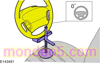
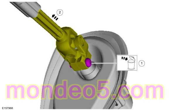
NOTICE: Do not allow the steering column shaft to rotate while disconnected from the gear or damage to the clockspring may occur. If there is evidence that the steering column shaft has rotated, remove and recenter the clockspring. Refer to Section 501-20B.
WARNING:
Do not reuse steering column shaft bolts. This may result in fastener failure and steering column shaft detachment or loss
of steering control. Failure to follow this instruction may result in serious injury to vehicle occupant(s).

NOTE: Have an assistant pull the brake booster and master cylinder assembly forward to allow the brake pedal and bracket to clear the brake booster studs during removal and installation.
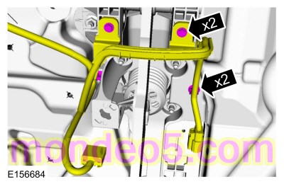
Torque : 23 Nm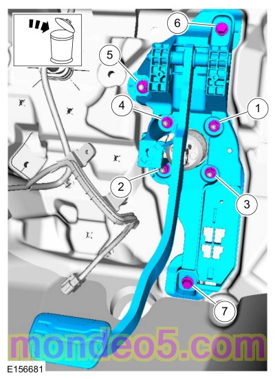
Installation
Copyright © Ford Motor Company