| 419-01A Perimeter Anti-Theft Alarm | 2013 - 2014 Fusion |
| Description and Operation | Procedure revision date: 11/27/2012 |
System Operation
System Diagram
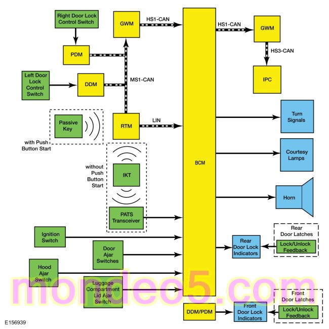
Network Message Chart
IPC Network Input Messages
| Broadcast Message | Originating Module | Message Purpose |
|---|---|---|
| Perimeter alarm chime request | BCM | Used by the IPC to sound the perimeter alarm chime during the 12-second delay. |
BCM Network Input Messages
| Broadcast Message | Originating Module | Message Purpose |
|---|---|---|
| RKE data | RTM | Used by the BCM to arm/disarm the perimeter alarm or to activate/deactivate the panic alarm. |
| Door lock switch status | DDM | Used by the BCM to arm/disarm the perimeter alarm. |
Anti-Theft - Perimeter
Perimeter Alarm
The BCM controls the operation of the perimeter alarm. It monitors inputs from the RKE system, the passive entry system (if equipped), the power door lock system, the PATS and the ignition status to determine when to arm the perimeter alarm.
The BCM monitors all of the door ajar switches, the luggage compartment lid ajar input, the hood ajar switch and the ignition status to determine when to activate the perimeter alarm. When the BCM detects an input indicating an unauthorized entry into the vehicle, the BCM activates the perimeter alarm by sounding the horn and flashing all the turn signals and interior courtesy lamps at regular intervals.
The BCM monitors the RKE system, the passive entry system (if equipped), and the PATS to determine when to disarm the perimeter alarm.
A switch inhibit feature temporarily disables the door lock control switches and the interior luggage compartment lid release
switch 20 seconds after the vehicle is electronically locked. For detailed information of the switch inhibit feature,
Refer to:
Handles, Locks, Latches and Entry Systems - System Operation and Component Description
(501-14 Handles, Locks, Latches and Entry Systems, Description and Operation).
Additionally, there is a door lock
LED
indicator located on each door window sill. The indicators provide lock/unlock indication for each door. They illuminate
when the door is locked and are off when the door is unlocked. For detailed information of the door lock
LED
indicators,
Refer to:
Handles, Locks, Latches and Entry Systems - System Operation and Component Description
(501-14 Handles, Locks, Latches and Entry Systems, Description and Operation).
Visual and audible feedback is also provided when locking or unlocking the vehicle. For detailed information of the vehicle
locking and unlocking feedback,
Refer to:
Handles, Locks, Latches and Entry Systems - System Operation and Component Description
(501-14 Handles, Locks, Latches and Entry Systems, Description and Operation).
Arming The Perimeter Alarm
The perimeter alarm is ready to arm any time the ignition is off. The perimeter alarm pre-arms when any of the following actions are performed:
Once the system is pre-armed, there is a 20-second countdown before the perimeter alarm is armed. Each entry point to the vehicle (hood, door and luggage compartment lid) is armed separately and must be closed before that entry point begins the 20-second countdown to become armed. If all entry points are closed, the turn signals flash upon locking indicating that all entry points are entering the 20-second countdown.
Perimeter Alarm Activation
The perimeter alarm has a 12-second delay when the driver front door is opened without using a RKE transmitter, the keyless entry keypad (if equipped) or a passive key (if equipped) to unlock the vehicle. During the delay, a chime sounds. If the perimeter alarm is not disarmed within the 12-second delay, the alarm activates.
The perimeter alarm activates when any of the following actions are performed:
The perimeter alarm only activates 10 times per arming cycle. After that, the alarm does not activate. To enable the perimeter alarm again, disarm the perimeter alarm and then arm it again.
Disarming The Perimeter Alarm
The perimeter alarm disarms when any of the following actions are performed:
Component Description
Door Latch
The door ajar switch, the lock/unlock solenoid and the lock/unlock status input switch are part of the door latch and not serviceable separately.
The door ajar switch is monitored by the
BCM
and the primary function is for the courtesy lamps system.
Refer to:
Interior Lighting - System Operation and Component Description
(417-02 Interior Lighting, Description and Operation).
The lock/unlock solenoid is controlled by the
BCM
for locking and unlocking the door.
Refer to:
Handles, Locks, Latches and Entry Systems - System Operation and Component Description
(501-14 Handles, Locks, Latches and Entry Systems, Description and Operation).
The lock/unlock status input switch is used to illuminate the door lock status indicator.
Refer to:
Handles, Locks, Latches and Entry Systems - System Operation and Component Description
(501-14 Handles, Locks, Latches and Entry Systems, Description and Operation).
Copyright © Ford Motor Company