| 413-01 Instrumentation, Message Center and Warning Chimes | 2013 - 2014 Fusion |
| Description and Operation | Procedure revision date: 07/10/2013 |
System Operation
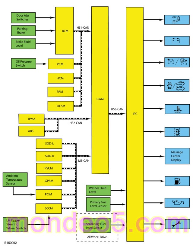
System Diagram
Network Message Chart
Module Network Input Messages - IPC
| Broadcast Message | Originating Module | Message Purpose |
|---|---|---|
| Autopark status | Parking Aid Module (PAM) | Input used to control the parking aid messages displayed in the message center. |
| AWD service required | PCM | Input used for the AWD component to control the powertrain malfunction (wrench) message center indicator. |
| AWD locking status | PCM | Input used to display the AWD messages. |
| Body service required request | BCM | Input used for the BCM controlled system faults input to control the powertrain malfunction (wrench) message center indicator. |
| Brake fluid level low message request | BCM | Input used to display the message center brake system messages. |
| Brake pedal applied | BCM | Input used to display the not in park warning message. |
| Brake warning indicator request | ABS module | Input used to display the electric parking brake message center warning messages. |
| Brake (red) warning indicator request | ABS module | Input used to display the message center brake system messages. Also used to display the electric parking brake message center warning messages. |
| Charging system indication request | BCM | Input used to control the charging system and load shed message center warning indicator and warning messages. |
| Check fuel fill inlet message request | PCM | Input used to display the check fuel fill inlet message. |
| Child lock message display request | BCM | Input used to display the child lock system fault message. |
| Cross traffic alert left status | SODL | Input used to control the blind spot information system message center indicator. |
| Cross traffic alert right status | SODR | Input used to control the blind spot information system message center indicator. |
| Cruise control set speed | PCM | Input used to control the cruise control set speed displayed in the message center. |
| Cruise control status | PCM | Input used to control the cruise control message center indicator and message display based on the system status. |
| Cruise control override | PCM | Input used to control the adaptive cruise control set speed display when the cruise control in overridden by the driver. |
| Door ajar status | BCM | Input used to control the door ajar message center indicator. |
| Driver door ajar status | BCM | Input used to display the not in park warning message. |
| EPAS failure | PSCM | Input used to control the service power steering message display. |
| Engine coolant temperature data | PCM | Input used to control the temperature gauge and the over-temperature message center indicator. |
| Engine oil life | PCM | Input used for the oil life display. |
| Engine oil life reset | PCM | Input used to confirm oil life reset. |
| Engine overheat indication request | PCM | Input used to control the temperature gauge and the over-temperature message center indicator. |
| Engine rpm data | PCM | Input used to control the low oil pressure message center warning indicator. |
| Engine service required request | PCM | Input used for the powertrain Electronic Throttle Control (ETC) component to control the powertrain malfunction (wrench) message center indicator. |
| Fuel maintenance mode display | PCM | Input used to display the fuel maintenance mode message. |
| Gear lever position | PCM | Input used to display the active park assist messages. |
| Ignition status | BCM | Ignition RUN, START and accessory states required for the IPC operating modes and fault reporting. Also used to display the not in park warning message. |
| Intelligent Access (IA) system message display | BCM | Input used to display the Intelligent Access (IA) no key detected, place key in backup slot and accessory power active message center warning displays. |
| Lane departure warning indicator request | IPMA | Input used to control the lane departure warning system indicator. |
| Lane departure warning system status display | IPMA | Input used to control the display of lane departure warning system message center warning messages. |
| Life cycle mode | BCM | Input used to indicate whether the vehicle is set in factory mode or transport mode to display the appropriate message and power down items such as the PRNDL at key off to conserve the battery. |
| Object entrapped message | OCSM | Input used to display the remove objects near the passenger seat warning message. |
| Oil pressure warning indicator request | PCM | Input used to control the low oil pressure message center warning indicator. |
| Parking aid status | Parking Aid Module (PAM) | Input used to display the active park assist messages. |
| Parking brake status | BCM | Input used to display the message center brake system messages. Also used for the display of the electric parking brake message center warning messages. |
| Perimeter alarm chime request | BCM | Input used to display the perimeter alarm message when the vehicle is entered before deactivating the perimeter alarm. |
| Powertrain cooling message request | PCM | Input used to display the reduced power to cool the engine on the Gasoline Turbo Direct Injection (GTDI) engines. |
| Remote start status | BCM | Input used to control the remote start active message display. |
| Reverse gear state | PCM | Input used to display the active park assist messages. |
| Starting system fault message request | PCM | Input used to display starting system messages. |
| Stability-traction control chime request | ABS module | Input used to control the service AdvanceTrac® and traction control off warning displays. Also used to control the traction control on/off status messages. |
| Stability-traction control disabled indicator request | ABS module | Input used to control the traction control on/off status messages. |
| Steering wheel lock message request | BCM | Input used to control the steering wheel lock system messages. |
| Stop/start message request | PCM | Input used to control the auto stop/start message display. |
| Transmission fault message request | PCM | Input used to display the transmission over-temperature and fault messages. |
| Transmission gear display actual | PCM | Input used to display the not in park warning message. |
| Transmission service required | PCM | Input used for the transmission component to control the powertrain malfunction (wrench) message center indicator. |
| Transmission shift indicator | PCM | Input used to control the upshift message center indicator. |
| Vehicle dynamics SOS | ABS | Input used to control the spin-out detected message. |
| Vehicle speed | PCM | Input used to display the not in park warning message. |
Auto Stop-Start Message Center Displays
The IPC provides the auto stop-start message center indicator along with multiple message displays at various times throughout the auto stop-start system operation to inform the driver of the system status and to provide direction as to the driver intervention required. The IPC receives the stop/start message request from the GWM over the High Speed Controller Area Network 1 (HS1-CAN). The GWM receives the stop/start message request from the PCM over the High Speed Controller Area Network 3 (HS3-CAN).
AWD Message Display
The IPC provides message center messages to inform the driver of the status of the AWD . The IPC receives the AWD locking status message from the GWM over the High Speed Controller Area Network 1 (HS1-CAN). The GWM receives the AWD locking status message from the PCM over the High Speed Controller Area Network 3 (HS3-CAN).
Blind Spot Monitoring System (BLIS) Off Message Center Indicator
The IPC provides a message center indicator to inform the driver that the Blind Spot Monitoring System (BLIS) is turned off. The IPC receives the cross traffic alert left status and cross traffic alert right status messages from the SODL and SODR through the GWM over the High Speed Controller Area Network 3 (HS3-CAN).
Brake System Message Displays
The IPC provides brake system displays for the following concerns and status:
When the parking brake is applied, the BCM sends the parking brake status to the GWM over the High Speed Controller Area Network 1 (HS1-CAN). The GWM gateways the message to the IPC over the High Speed Controller Area Network 3 (HS3-CAN) to illuminate the brake warning indicator and turn on the parking brake applied message in the message center.
When a low brake fluid level condition exists, the BCM sends the brake fluid level low message request to the GWM over the High Speed Controller Area Network 1 (HS1-CAN). The GWM gateways the message to the IPC over the High Speed Controller Area Network 3 (HS3-CAN) to illuminate the brake warning indicator and turn on the brake fluid level low message in the message center.
When an ABS or parking brake system concern exists, the ABS module sends the brake (red) warning indicator request message to the GWM over the High Speed Controller Area Network 2 (HS2-CAN). The GWM sends the brake (red) warning indicator request message to the IPC over the High Speed Controller Area Network 3 (HS3-CAN) to illuminate the ABS warning indictor and to turn on the check brake system message center warning display.
Charging System Message Center Displays
The IPC provides a charging system message center indicator along with message displays indicating the status of the charging system. When a fault is present in the charging system, the BCM sends the charging system indication request to display message center warning messages and the charging system message center warning indicator.
The IPC receives the charging system indication request message from the GWM over the High Speed Controller Area Network 3 (HS3-CAN). The GWM receives the charging system indication request message from the BCM over the High Speed Controller Area Network 1 (HS1-CAN).
Compass Display
On the base and mid-level IPC , the compass is displayed as a 1 or 2 character display in the message center that indicates the current direction of the vehicle (N, NE, E, SE, S, SW, W, or NW). On the high-level IPC , the compass can be displayed as a virtual compass along with the 1 or 2 character display. The IPC receives the GPS compass direction from the GWM over the High Speed Controller Area Network 3 (HS3-CAN). The GWM receives the GPS compass direction from the GPSM over the Medium Speed Controller Area Network (MS-CAN).
Cruise Control Message Center Indicator
The IPC uses the following messaged inputs to control the cruise control message center indicator:
The IPC receives the cruise control messages from the GWM over the High Speed Controller Area Network 3 (HS3-CAN). The GWM receives the cruise control messages from the PCM over the High Speed Controller Area Network 1 (HS1-CAN).
Cruise Control Message Center Indicator
The IPC uses cruise control status, cruise control set speed and cruise control override messaged inputs to control the cruise control message center indicator. When the ECO mode is active, the cruise control system allows a wider range of vehicle speed loss before accelerating to maintain the selected speed for better economy. The IPC receives the cruise control messages from the GWM over the High Speed Controller Area Network 3 (HS3-CAN). The GWM receives the cruise control messages from the PCM over the High Speed Controller Area Network 1 (HS1-CAN).
Door Ajar Indication Message Center Displays
The IPC provides a door ajar message center indicator along with message displays to indicate the status of the doors or luggage compartment lid. The BCM monitors each of the ajar inputs and sends a door ajar status message to the GWM over the High Speed Controller Area Network 3 (HS3-CAN). The IPC receives the door ajar status message from the GWM over the High Speed Controller Area Network 1 (HS1-CAN) to display the specific ajar message center warning indicator and corresponding warning message.
Electric Park Brake Message Display
The IPC provides messages to indicate the status of the electric parking brake system. The messages displayed are a combination of informational messages, warning and system fault messages. The IPC uses messages sent from the ABS module and BCM to control the messages displayed. The IPC receives all messages from the GWM over the High Speed Controller Area Network 3 (HS3-CAN). The GWM receives the parking brake message request, brake warning indicator request and the brake (red) warning indicator request from the ABS module over the High Speed Controller Area Network 2 (HS2-CAN). the GWM receives the red brake warning indicator request from the BCM over the High Speed Controller Area Network 1 (HS1-CAN).
Engine Over-Temperature Message Center Warning Indicators
The IPC provides a message center warning indicator to alert the driver the engine is over temperature. The IPC receives the engine overheat indication request and the engine coolant temperature data from the GWM over the High Speed Controller Area Network 3 (HS3-CAN). The GWM receives the engine overheat indication request and the engine over-temperature message from the PCM over the High Speed Controller Area Network 1 (HS1-CAN).
Factory-Transport Mode Display
During vehicle build, some modules, such as the IPC and the BCM , are set in factory mode. While in the factory mode the IPC displays FACTORY MODE CONTACT DEALER in the message center. If the vehicle is set in factory mode, the system does not automatically exit the mode and must be manually set to either the transport or normal operation mode.
When the vehicle build is complete, the vehicle is set to transport mode. While in transport mode, the IPC displays TRANSPORT MODE CONTACT DEALER in the message center. Transport mode is used to reduce the drain on the battery during longer periods where the vehicle is not used. Various systems may be altered or are disabled when in the transport mode. The vehicle automatically reverts to normal operation mode after being driven 80 km (50 mi).
The IPC receives the life cycle mode message from the GWM over the High Speed Controller Area Network 3 (HS3-CAN). The GWM receives the life cycle mode message from the BCM over the High Speed Controller Area Network 1 (HS1-CAN).
Fuel System Message Displays
The IPC provides a check fuel fill inlet message to warn the driver there is a problem with the fuel fill inlet pipe resulting from a significant evaporative emission leak following vehicle refueling.
The IPC receives the check fuel fill inlet message request from the GWM over the High Speed Controller Area Network 3 (HS3-CAN). The GWM receives the check fuel fill inlet message request from the PCM over the High Speed Controller Area Network 1 (HS1-CAN).
Lane Departure Warning System Message Center Displays
The lane departure warning system combines the lane keeping alert and lane keeping aid systems. The lane keeping alert system alerts the driver of unintentional drifting outside of the lane and the lane keeping aid system corrects the vehicle steering to keep the vehicle in the center of the lane. The IPC provides a lane departure warning display as an overhead view of the vehicle in the middle of a lane with right and left lane markers to indicate the vehicle position with relation to the lane markings as well as overlay or popup messages to alert the driver when they are drifting out of their lane. The lane markers change color to indicate the condition associated with a specific condition and action or warning as controlled by the lane departure warning system. The IPC also provides a lane departure warning system message center off indicator to inform the driver that the lane departure warning system is turned off. When the lane departure warning system is turned off, the IPC turns on the lane departure warning system message center indicator and turns off the lane departure warning system display.
The IPC receives both the lane departure warning system status display message and the lane departure warning indicator request from the GWM over the High Speed Controller Area Network 3 (HS3-CAN).
The GWM receives the lane departure warning system status display message and the lane departure warning indicator request from the Image Processing Module-A (IPMA) over the High Speed Controller Area Network 2 (HS2-CAN).
Low Fuel Message Center Warning Indicator
To supplement the fuel gauge indication, the IPC provides the low fuel message center warning indicator. When the fuel level reaches 1/16 tank and 1/8 tank for MyKey® users, the IPC turns on the low fuel message center warning indicator.
Low Oil Pressure Message Center Warning Indicator
The engine oil pressure switch is hardwired to the PCM . The PCM provides the engine oil pressure indicator request and engine rpm data to the GWM over the High Speed Controller Area Network 1 (HS1-CAN). The IPC receives the oil pressure warning indicator request and engine rpm data from the GWM over the High Speed Controller Area Network 3 (HS3-CAN). The IPC requires engine rpm above 400 rpm before the message center displays the low oil pressure message center indicator.
MyKey® Function Message Displays
The IPC provides message center displays for the MyKey® feature. MyKey® displays are controlled through the IPC software based on the MyKey® settings configured through the message center and the type of key in use (MyKey® or administrator key). The MyKey® function also uses other messages received by the IPC for other indications such as vehicle speed for speed limiter displays.
Odometer
The IPC receives the odometer count message from the GWM over the High Speed Controller Area Network 3 (HS-CAN). The GWM receives the odometer count from the PCM over the High Speed Controller Area Network 1 (HS1-CAN). The IPC monitors the odometer count input from the GWM and commands the odometer with a digital display in the message center.
Oil Life Message Center Display
The IPC provides message center messages to inform the driver about the oil life status and when an oil change is required. The duration of the interval between oil changes is calculated in the PCM and varies due to driving conditions. The PCM assumes a base mileage of 16,090 km (10,000 mi) or 1 year for normal driving. However, this number is adjusted down for conditions such as high engine temperature, high engine rpm, use of flex fuel and possibly low oil level. The PCM calculates and provides the engine oil life percent message to the IPC . The IPC further converts the remaining oil life using the driver's configured oil life start value and displays the oil life percentage, indicating the remaining oil life. The oil change minder can be reset at any time by the driver.
The IPC receives the engine oil life message and engine oil life reset request from the GWM over the High Speed Controller Area Network 3 (HS3-CAN).
The PCM receives the engine oil life reset request from the GWM over the High Speed Controller Area Network 3 (HS3-CAN).
The GWM receives the engine oil life message from the PCM over the High Speed Controller Area Network 1 (HS1-CAN).
The GWM receives the engine oil life reset message from the IPC over the High Speed Controller Area Network 1 (HS1-CAN).
Outside Air Temperature Display
The Ambient Air Temperature (AAT) sensor is hardwired to the PCM through separate input and return circuits. The PCM provides a reference voltage to the Ambient Air Temperature (AAT) sensor and monitors the change in voltage resulting from changes in resistance as determined by outside air temperature. The PCM filters the ambient air temperature input and sends the data to the GWM through the Medium Speed Controller Area Network (MS-CAN). The GWM sends the air ambient temperature filtered message to the IPC over the High Speed Controller Area Network 3 (HS3-CAN).
The PCM is programmed to update the messaged outside temperature data at different rates depending on several criteria to prevent false temperature displays due to a condition known as heat soaking. Heat soaking is where the outside air temperature is hotter in the location of the Ambient Air Temperature (AAT) sensor than the actual outside air temperature.
When the sensed outside temperature rises, the display updates slowly at varying rates based on vehicle speed. When the sensed outside temperature drops, the display updates more quickly following the drop experienced by the Ambient Air Temperature (AAT) sensor.
Parking Aid System Message Displays
The IPC provides messages to indicate the status of the parking aid system. The IPC receives the parking aid status messages from the GWM over the High Speed Controller Area Network 3 (HS3-CAN). The GWM receives the parking aid status messages from the Parking Aid Module (PAM) over the High Speed Controller Area Network 1 (HS1-CAN).
Passive Key And Immobilizer System Message Displays
The IPC provides the passive key and immobilizer system message center display to indicate the key is in the luggage compartment, the key is left in the vehicle, no key is detected, accessory power is active, to inform the driver a steering lock fault exists, to press the brake to start the vehicle or to place the key in the backup slot. The IPC uses the push button start message input from the BCM to display multiple message center messages.
The IPC receives the push button start message display data from the GWM over the High Speed Controller Area Network 3 (HS3-CAN).
The GWM receives the push button start message display data from the BCM over the High Speed Controller Area Network 1 (HS1-CAN).
Perimeter Alarm Message Display
The IPC provides a display to indicate the perimeter alarm has been activated and to start the vehicle to stop the alarm. The IPC receives the perimeter alarm chime request message from the GWM over the High Speed Controller Area Network 3 (HS3-CAN). The GWM receives the perimeter alarm chime request from the BCM over the High Speed Controller Area Network 1 (HS1-CAN).
Power Child Lock-Switch Inhibit And Low Key Fob Message Displays
The IPC provides a power child lock warning to inform the driver the child lock feature did not function properly. The power child lock feature is activated through the rear window lockout switch on the driver side master window control switch.
The IPC provides a switch inhibit warning to notify the driver that some switches have been purposely inhibited and are inoperative. For security purposes, interior switches are inhibited by the BCM 20 seconds after the vehicle is electronically locked and prevents someone from using a stick (or other object) through an open window and activating the switch.
The IPC provides a low key fob battery warning to alert the driver the key fob battery needs to be replaced. The low key fob battery warning is not displayed in RUN or START modes if the power child lock warning is active to prevent the BCM from cycling between the two warnings, causing the chime associated with the power child lock warning from repeatedly sounding every 4 seconds.
Powertrain Cooling Message Display
On vehicles equipped with a Gasoline Turbo Direct Injection (GTDI) engine, the IPC provides a message to inform the driver that vehicle performance is reduced to allow the engine to cool. This feature is part of the smart cooling function in the PCM and provides powertrain cooling protection under high ambient temperature conditions.
The IPC receives the powertrain cooling message request from the GWM over the High Speed Controller Area Network 3 (HS3-CAN). The GWM receives the powertrain cooling message request from the PCM over the High Speed Controller Area Network 1 (HS1-CAN).
Powertrain Malfunction (Wrench) Message Center Indicator
The IPC provides a powertrain malfunction (wrench) message center indicator to indicate transmission, Electronic Throttle Control (ETC), AWD , and BCM concerns.
The IPC receives all the required messages from the GWM over the High Speed Controller Area Network 3 (HS3-CAN).
The GWM receives the body service required message from the BCM over the High Speed Controller Area Network 1 (HS1-CAN).
The GWM receives the transmission service required, engine service required and AWD service required messages from the PCM over the High Speed Controller Area Network 1 (HS1-CAN).
Remote Start Message Displays
The IPC provides remote start messages to inform the driver the vehicle is in the remote start active state and how to change the state to a driveable state. The remote start message display is active as soon as the vehicle is remote started (that is, the engine is running, but the ignition status is off).
The IPC receives the remote start status message from the GWM over the High Speed Controller Area Network 3 (HS3-CAN). The GWM receives the remote start status message from the BCM over the High Speed Controller Area Network 1 (HS1-CAN).
Shift To Park Message Display
The IPC provides a shift to park message to inform the driver the vehicle is not in PARK (P) under 2 sets of conditions. First, the IPC displays the shift to park message if the selector lever is not in PARK (P), the ignition is OFF and the driver door is open or ajar. Second, the IPC displays the shift to park message if the selector lever is not in PARK (P), the ignition is ON or in ACC, the driver door is open or ajar and the brake pedal is not applied with vehicle speed less than 5 km/h (3 mph). The IPC uses multiple messages to control the shift to park message.
The IPC receives all required messages from the GWM over the High Speed Controller Area Network 3 (HS3-CAN).
The GWM receives the transmission gear display, brake pedal applied and vehicle speed messages from the PCM over the High Speed Controller Area Network 1 (HS1-CAN).
The GWM receives the driver door ajar status and ignition status message from the BCM over the High Speed Controller Area Network 1 (HS1-CAN).
The IPC also uses the park position detect input to determine whether the vehicle is in PARK (P) along with the transmission gear display message.
See Park Position Detect Switch component description.
Refer to:
Instrument Panel Cluster (IPC) - System Operation and Component Description
(413-01 Instrumentation, Message Center and Warning Chimes, Description and Operation).
SRS Message Display
The IPC provides a message center message to alert the driver when there is an object blocking the operation of the OCS under the passenger seat.
The IPC receives the object entrapped message from the GWM over the High Speed Controller Area Network 3 (HS3-CAN). The GWM receives the object entrapped message from the OCSM over the High Speed Controller Area Network 2 (HS2-CAN).
Stability-Traction Control-Spinout Detection System Message Displays
The IPC provides a stability-traction control system message center message to indicate the stability-traction control system has a fault and requires service.
When a fault condition exists in the stability-traction control system, the ABS module sets a DTC and sends the stability-traction control chime request to the GWM over the High Speed Controller Area Network 2 (HS2-CAN). The GWM sends the stability-traction control chime request to the IPC over the High Speed Controller Area Network 3 (HS3-CAN).
The spinout detection feature activates the hazard indicator to alert other vehicles approaching the vehicle following a spin-out, potentially reducing the risk of collision, especially in low visibility weather conditions. A spinout is defined as a slip angle greater than 40 degrees followed by 5 seconds of vehicle at rest.
When a spinout is detected, the system activates the hazard indicator and the IPC displays a message to inform the driver that the hazards have been turned on. The IPC receives the vehicle dynamics SOS message from the GWM over the High Speed Controller Area Network 3 (HS3-CAN). The GWM receives the vehicle dynamics SOS message from the ABS module over the High Speed Controller Area Network 2 (HS2-CAN).
Starting System Message Display
The IPC provides a starting system message display to inform the driver of further actions required to start the engine or to explain the reason for the inability to start the engine on. The IPC receives the starting system fault message request from the GWM over the High Speed Controller Area Network 3 (HS3-CAN). The GWM receives the starting system fault message request from the PCM over the High Speed Controller Area Network 1 (HS1-CAN).
Steering System Message Displays
The IPC provides a message center message to indicate there is an EPAS system concern. When a fault exists in the EPAS , the PSCM sends a request to the IPC through the GWM . The IPC provides a message center message to indicate a fault in the steering wheel locking system.
The IPC receives the EPAS failure message and the steering wheel lock message request through the GWM over the High Speed Controller Area Network 3 (HS3-CAN).
The GWM receives the EPAS failure message from the PSCM over the High Speed Controller Area Network 2 (HS2-CAN).
The GWM receives the steering wheel lock message request from the BCM over the High Speed Controller Area Network 1 (HS1-CAN).
Tire Pressure Monitoring System (TPMS) Message Displays
The IPC provides message center displays to indicate the TPMS sensor training status or a malfunction in the TPMS .
The IPC receives the tire pressure status message from the GWM over the High Speed Controller Area Network 3 (HS3-CAN). The GWM receives the tire pressure status message from the BCM over the High Speed Controller Area Network 1 (HS1-CAN).
Transmission Fault Message Display
The IPC provides transmission messages to inform the driver the transmission faults exist or transmission temperature is high.
The IPC receives the transmission fault message request from the GWM over the High Speed Controller Area Network 3 (HS3-CAN). The GWM receives the transmission fault message request from the PCM over the High Speed Controller Area Network 1 (HS1-CAN).
Component Description
Engine Oil Pressure Switch
Without oil pressure, the engine oil pressure switch is a normally open switch. The PCM provides a reference voltage to the engine oil pressure switch when the ignition is in RUN. With the engine running and low or no oil pressure, the engine oil pressure switch remains open. The PCM detects no change in the reference voltage and provides a request to the IPC to illuminate the low oil pressure warning indicator. With the engine running and sufficient oil pressure, the engine oil pressure switch closes, pulling the reference voltage low. The PCM detects the low reference voltage and provides a request to the IPC to turn off the low oil pressure warning indicator.
Steering Wheel Switch - Message Center
The message center switch is the upper LH steering wheel switch and is comprised of 5 buttons. The message center switch uses different resistance values associated with each specific button. The SCCM sends out a reference voltage to the upper LH steering wheel switch on the input circuit and monitors the voltage drops. The voltage drop varies depending upon the resistance of the specific button pressed, providing indication to the SCCM which button is pressed.
Copyright © Ford Motor Company