| 413-00 Instrument Panel Cluster (IPC) and Panel Illumination | 2013 - 2014 Fusion |
| Description and Operation | Procedure revision date: 08/29/2012 |
System Operation
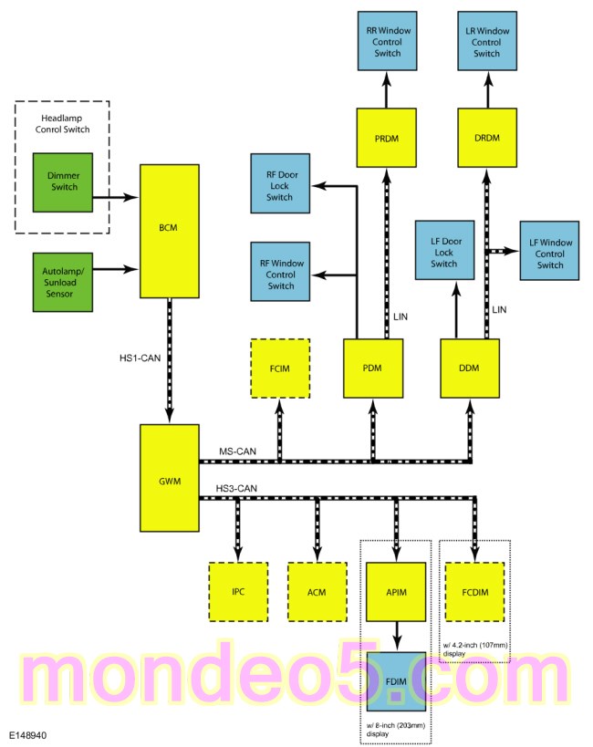
System Diagram - Networked Illumination
Network Message Chart
Module Network Input Messages - FCIM , DDM , PDM , IPC , ACM , APIM , FCDIM
| Broadcast Message | Originating Module | Message Purpose |
| Illumination Dimming Level | BCM | Used to command the illumination dimming level for networked modules and outputs that are hardwired to networked modules. |
Networked Illumination Operation
The system-wide illumination dimming level is determined by the BCM . Based on the ambient light level input from the autolamp/sunload sensor and the requested illumination dimming level input from the dimmer switch, the BCM calculates the correct dimming level. The BCM sends the illumination dimming level message to the GWM on High Speed Controller Area Network 1 (HS-CAN 1). The GWM then distributes the message to the FCIM , DDM and PDM on the Medium Speed Controller Area Network (MS-CAN) and the IPC , ACM , APIM and FCDIM on the High Speed Controller Area Network 3 (HS-CAN 3). The DDM and PDM send the illumination dimming level data to the Driver Rear Door Module (DRDM) and Passenger Rear Door Module (PRDM) via LIN circuits.
The receiving modules use the illumination dimming level message to determine the backlighting intensity of internal and external harwired illumination sources. If a module does not receive the illumination dimming level message or the data received is deemed invalid, the module sets a DTC in continuous memory and defaults to full nighttime intensity.
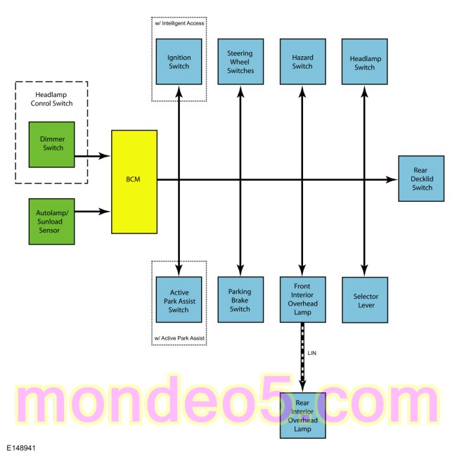
System Diagram - Non-Networked Illumination
Non-Networked Illumination Operation
Based on the ambient light level input from the autolamp/sunload sensor and the requested illumination dimming level input from the dimmer switch, the BCM calculates the correct dimming level for the hardwired illumination sources. The BCM provides a pulse-width modulated voltage to all hardwired illumination sources on 1 circuit.
Component Description
Dimmer Switch
The dimmer switch is a momentary contact switch that is integral to the headlamp switch. The headlamp switch is hardwired to the BCM . When the dimmer switch is pressed up or down, the switch completes a ground circuit to the BCM corresponding to the desired action (increase or decrease illumination brightness).
Body Control Module (BCM)
The
BCM
is used to calculate the illumination dimming level for all illumination sources. The illumination voltage circuit from the
BCM
is protected by a Field Effect Transistor (FET). This is used to turn the output off to protect the
BCM
from damage in the event that an excessive current draw is detected on the illumination voltage circuit. For a full description
of Field Effect Transistor (FET) protection,
Refer to:
Module Controlled Functions - System Operation and Component Description
(419-10 Multifunction Electronic Modules, Description and Operation).
Copyright © Ford Motor Company